Spur Gear with Hub Machining Case Study: From Stepped Blank to Keyway and Tooth Hardening
Blog 2026-07-29
| Part Name | Spur Gear with Hub |
|---|---|
| Material | 40Cr Steel Round Bar (ϕ120 × 74 blank) |
| Critical Tolerances | Bore ϕ32H7, Gear OD ϕ111h11 |
| Surface Roughness | Ra 1.6μm |
| Core Equipment | Brother TC-S2A CNC Lathe, Ningjiang YK3610IV CNC Hobbing Machine |
This case study traces the actual process route we used to deliver a 40Cr steel spur gear with hub, from a ϕ120 round bar blank to the finished part. We adjusted all dimensions and project specifics to protect customer confidentiality while preserving the engineering context.
Technical Challenges in Spur Gear with Hub Machining
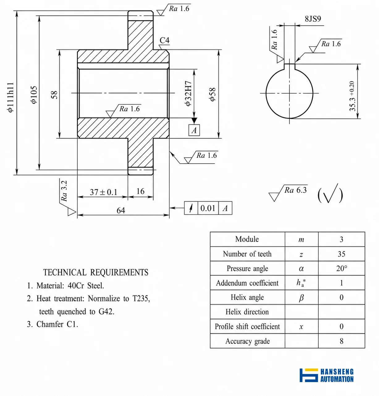
For this spur gear with hub, three requirements stood out as the primary cost and quality drivers in the machining sequence.
Achieving H7 Bore Tolerance in the Gear Hub
The bore is called out at ϕ32H7, a tolerance zone of +0.025/0 mm. Paired with a surface finish of Ra 1.6 μm, this isn’t a hole you can simply ream and ship. On 40Cr alloy steel, hitting both size and finish consistently demands a rigid boring bar, a sharp insert with the right chipbreaker geometry, and a stable, low-feed finishing pass. Any hint of chatter or insert wear immediately pushes the bore out-of-round or scuffs the surface beyond spec.
40Cr Steel – Hardness vs. Toughness
40Cr (a medium-carbon chrome steel comparable to AISI 5140) offers decent hardenability, but in its as-supplied state, the blank is too soft to resist tooth flank pitting and wear. Through-hardening the entire part would leave the hub brittle under shock loads. The answer is a dual-condition treatment: a quench-and-temper cycle to establish a tough, ductile core across the blank, followed by localized tooth surface hardening. The challenge is metallurgical—achieving a hard case on the flanks, a tough transition at the root, and a resilient hub without gross distortion. The machining sequence has to anticipate and compensate for that distortion.
Ensuring Concentricity Between the Hub Bore and Gear OD
The part only functions if the pitch circle runs true to the bore axis. On the print, the gear outside diameter is ϕ111h11, and its runout to ϕ32H7 directly dictates gear quality—transmission error, noise, and uneven load distribution. The real-world pain point is that this part sees multiple setups: turning, hobbing, and post-heat-treat hard finishing. If the turned blank relies on the OD as a datum while hobbing picks up the bore, accumulated eccentricity can easily scrap the gear. The entire fixture and datum strategy must force the generated teeth to be concentric with the final bore axis, not just the pre-machined blank OD.
The 3-Stage Heat Treatment Strategy for Spur Gear with Hub Manufacturing
Heat treatment for a hub-type spur gear isn’t a single batch operation. It’s three distinct interventions, each positioned at a specific point in the machining sequence. Misplace any one of them, and you end up fighting work hardening during turning or scrapping finished bores to post-heat distortion. For 40Cr, we settled on the following staged route.
Normalizing
Once the ϕ120 round bar is cut into a 74 mm blank, it is transferred to the furnace. 40Cr in its supply condition often carries residual stresses from the mill and an inconsistent microstructure. Normalizing at roughly 860°C, followed by still-air cooling, refines the grain and homogenizes the hardness across the blank.
From a machinist’s perspective, this step makes the material far more predictable during the heavy roughing cuts on the CNC lathe. Insert life stabilizes, and the risk of hitting a hard spot that chips a cutting edge drops significantly. Without it, the first roughing pass on the scale-covered OD can eat through carbide inserts at an unpredictable rate.
Quenching & Tempering (Q&T)
This stage sits right between rough turning and finish turning. We rough out the stepped hub profile, leaving a uniform 1.5 mm stock on all diameters and faces. The roughed blank then enters a box furnace for a full quench-and-temper cycle. Austenitizing, oil quench, and high-temperature tempering bring the core hardness to 220–250 HBW. The objective is a tough, ductile core through the entire cross-section—the hub, the web, and the root of every tooth.
At 250 HBW, the material offers enough strength to resist tooth bending fatigue while still absorbing shock loads at the hub without brittle failure. Crucially, Q&T introduces predictable distortion. Ovality and dimensional growth are unavoidable. By sequencing all finish turning after Q&T, we machine the ϕ32H7 bore and the ϕ111h11 gear OD to final tolerance on a thermally stable, stress-relieved blank.
High-Frequency Induction Hardening
With the gear teeth hobbed, only the flank surfaces require high hardness. We apply high-frequency induction heating locally to the tooth zone, rapidly raising the surface above transformation temperature, then quench and low-temperature temper. The specified flank hardness is 42–47 HRC. Because the heat-affected zone is confined to the tooth ring, the hub and the ϕ32H7 bore stay in their tough, tempered state. Localized heating also keeps overall part distortion to a minimum compared to a full through-hardening cycle. However, we still expect a few microns of growth at the pitch circle diameter.
If the drawing demands a tighter gear quality class, a final hard skiving or grinding pass after Process 80 corrects that residual shift. This staged approach—normalize for machinability, Q&T for core toughness, then induction harden for wear resistance—is what makes a 40Cr gear with a hub survive both impact and surface fatigue in service.
Step-by-Step CNC Machining Process for the Spur Gear with Hub
Every clamp change, every datum transfer, is built around one overriding objective: to guarantee that the finished gear teeth run concentrically to the ϕ32H7 bore axis.
Step 1: Rough CNC Turning
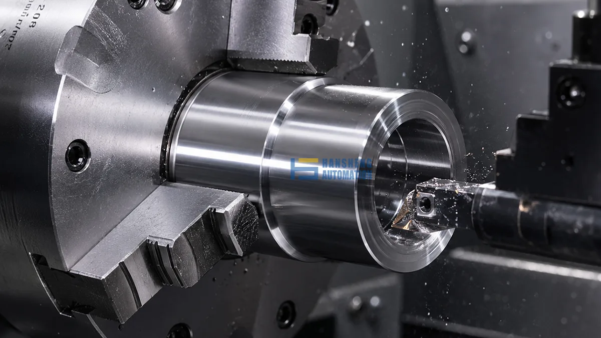
With the normalized blank measuring ϕ120 × 74 mm, the first chip-making operation runs on a Brother TC-S2A CNC lathe. The normalized condition keeps insert wear predictable during these heavy interrupted cuts.
One end of the blank is chucked on the ϕ58 hub spigot, leaving the majority of the length exposed. A 45° lead-angle turning tool faces the end, establishing a clean reference surface while leaving 1 mm of stock for later finishing. A 90° OD turning tool then roughs the main gear body diameter from ϕ120 down to ϕ113, leaving a generous 2 mm radial allowance on the ϕ111h11 finished OD. A ϕ30 twist drill roughs out the through-bore, opening the center for subsequent boring bar access toward the ϕ32H7 finished size.
Our machinists then flip the part and grip it on the roughed ϕ113 diameter. The second side is faced to bring the overall length to 66 mm. The opposite ϕ58 hub spigot is rough-turned to ϕ60, and the tooth-width land is cut to an 18 mm rough width, blocked out for the gear zone. At this point, all features are oversized, and the part is ready for the Q&T heat treatment cycle—where most of the dimensional drift will occur.
Step 2: Precision CNC Turning for Hub and Bore Datum Control
The blank returns to the Brother TC-S2A after quenching and tempering. Core hardness is now 220–250 HBW. The tooling setup switches from roughing inserts to finishing geometries, and the workholding process becomes strictly controlled.
First Setup: Finish-Turning the Long Hub End
The first precision setup grips the roughed main body diameter. The exposed long hub end is finish-turned: the face is cut to establish a total length of 65 mm, with a surface finish held to Ra 1.6 μm. The hub OD and the shoulder dimension of 37 ±0.1 mm are brought to final size in the same pass cycle, ensuring those axial datums are square to each other.
Critical Setup: Single-Clamping Finish Boring and Datum Control
The critical setup follows. The part is flipped and chucked on the ϕ58 hub OD—now a finished reference surface. The operator indicates the hub to keep runout within a few microns. In this single clamping, the tail end face is finish-turned, bringing the overall length to the final 64 mm with Ra 1.6 μm, and the tooth-width land is finished to 16 mm. Chamfers C1 and C4 are machined at this stage.
What makes this setup decisive is the bore. While the part is still gripped on the hub and aligned, a boring bar finishes the ϕ32H7 bore to tolerance—+0.025/0 mm—and Ra 1.6 μm. The same clamping produces the finished end face, the gear OD (to be completed in a subsequent pass on this machine or held for hobbing reference), and the bore.
The engineering rationale here is straightforward: if the bore and its gear-related datums are machined in separate setups, any chucking mismatch translates directly into eccentricity between the pitch circle and the axis of rotation. By finishing the bore in the same clamping that establishes the axial and radial reference surfaces, we lock in the concentricity and perpendicularity required for the hobbing operation that follows. This single setup rule—“To guarantee concentricity between the gear OD and the bore, finish machining must be completed in one clamping”—is the make-or-break decision on a hub-type spur gear.
With the bore and hub datums stable, the part now moves to the hobbing machine, where the tooth profile generation will rely entirely on the ϕ32H7 bore as its primary locating feature—not the OD. That datum hierarchy, established here at the lathe, is what turns a stepped blank into a ready-to-hob gear preform.
Step 3: CNC Gear Hobbing
With the bore and end face finished to final tolerance and surface finish on the lathe, the part transfers to a Ningjiang YK3610IV CNC hobbing machine. The datum strategy set at the turning stage now becomes operational. The blank is mounted on a precision-expanding mandrel that locates directly on the ϕ32H7 bore. An axial support face registers against the finished end face of the hub shoulder. Nothing is referenced off the gear OD—the hob generates the tooth profile exclusively around the bore axis, which is the functional rotation center of the assembled gear.
The 40Cr material’s quenched-and-tempered condition dictates the hob selection, feed rate, and number of passes (220–250 HBW). Tooth parameters—module, pressure angle, and helix angle—are dialed into the machine control. A roughing pass removes the bulk of the material from the tooth spaces, and a finishing pass brings the involute profile and tooth thickness to spec. Throughout the cycle, coolant floods the cutting zone to manage the thermal load and prevent hob wear from shifting the tooth geometry mid-cycle. The result is a toothed blank where the pitch circle runs concentric to the bore within the runout tolerance.
Step 4: Keyway Broaching & Final Operations
Deburring comes immediately off the hobbing machine. Gear teeth exit the hob with a fine burr along the tip edges and at the end faces where the hob breaks out. A bench operator removes these burrs by hand using a file and deburring knife, and applies the required tooth-end chamfer. For a hub-type gear, this is also the point where any sharp edges on the stepped shoulders and bore are broken. No machine can replace the tactile feedback of an experienced hand checking for a missed burr that could disrupt assembly or concentrate stress during service.
Keyway Broaching is sequenced after high-frequency induction hardening. Because induction hardening is localized to the tooth flanks, the bore and keyway region remain in the quenched-and-tempered condition at 220–250 HBW—still within the practical range for broaching. The part is fixtured on a vertical broaching machine, with the bore axis aligned to the broach travel. A single-pass broach cuts the 8JS9 keyway through the ϕ32H7 bore. Dimensional verification uses a go/no-go keyway plug gauge. A tight-fitting keyway is non-negotiable: this interface transmits torque between the gear hub and the shaft, and any clearance here directly becomes backlash or fretting at the shaft-hub connection. The finished gear now carries a precision bore, accurate teeth, and a verified keyway—ready to seat against its mating shaft shoulder without shimming or rework.
Inspection and Final Delivery for Custom Spur Gears
Comprehensive Dimensional and Gear Runout Inspection
Before palletizing and shipping, every gear batch undergoes a final dimensional audit checked strictly against the drawing tolerances. A CNC gear measuring center checks involute profile deviation, helix deviation, and cumulative pitch error against the specified gear quality class. Any tooth that drifts outside the tolerance band flags the entire hobbing setup for review. In parallel, the ϕ32H7 bore is re-verified with an air gauge or bore micrometer—checking not just diameter but roundness—and the 8JS9 keyway is confirmed with a go/no-go plug gauge. Runout between the pitch circle and the bore is dial-indicated on a mandrel; the number here is the ultimate verdict on whether the lathe-to-hobbing datum transfer succeeded.
Anti-Corrosion Packaging for Overseas Delivery
Parts that pass inspection are immediately coated with a solvent-cut rust preventative oil, with extra attention to the bore, keyway, and tooth flanks. Our logistics team wraps each gear in VCI paper, seals it in a poly bag, and nests it in closed-cell foam cut to the part profile. We then pack the custom crate with desiccant packs and shock-absorbing corner blocks. The packaging is designed for a container journey; when the overseas customer opens the box, the gear surfaces are corrosion-free and ready for assembly without additional cleaning.
Conclusion
Delivering a spur gear with hub to ϕ32H7 and ϕ111h11 tolerances on 40Cr is less about any single machine and more about the sequence. Rough and finish turning separated by quench-and-temper keeps the bore round when it matters. Finishing the bore, end face, and gear OD in one lathe clamping removes the stack-up error that makes gears run out. And inserting normalizing before the first rough cut, plus induction hardening only on the tooth flanks after hobbing, handles the metallurgical half of the problem before it becomes a dimensional one. Ultimately, a rigorously controlled process is what guarantees a high-quality product.
Looking for a reliable custom gear machining partner for your custom spur gears? Send us your 2D/3D drawings for a free DFM review and fast quote.
FAQ
40Cr steel (equivalent to AISI 5140 or DIN 41Cr4 alloy steel) is an excellent choice for transmission gears. It offers a perfect balance of strength, toughness, and hardenability. Through proper heat treatment (quenching and tempering), the gear core achieves high impact resistance, making it ideal for high-load mechanical applications.
Concentricity is critical for minimizing gear runout and noise. We achieve this through strict datum control. During the precision CNC turning stage, we use a single-setup method to machine the inner ϕ32H7 bore and the outer gear blank simultaneously. This ensures the bore and the gear’s outer diameter share the exact same geometric centerline before moving to the gear hobbing machine.
If the entire gear is hardened, it becomes too brittle and is prone to warping or cracking under shock loads. By isolating the hardening process to just the teeth via induction heating, we achieve a high surface hardness (42-47 HRC HRC) for maximum wear resistance. Meanwhile, the hub and core remain at 220-250 HBW, retaining the necessary toughness to absorb operational vibrations.
Yes, absolutely. In this case study, we utilized a precision broaching machine to cut an 8JS9 tolerance keyway. Depending on your assembly requirements, we can accommodate various internal features, including standard keyways, custom splines, set-screw holes, or tapped holes in the hub.
To provide an accurate and fast quote, please send us your 2D engineering drawings (PDF format) specifying dimensions, critical tolerances (like H7 bore), material preferences, and heat treatment requirements. Providing a 3D model (STEP/IGES) is also highly recommended. Our engineering team typically returns a free DFM review and quotation within 24 hours.