From 42CrMo Bar to 5-Grade Precision: A Complete Straight Bevel Gear Machining Process Case Sharing
Blog 2026-08-05
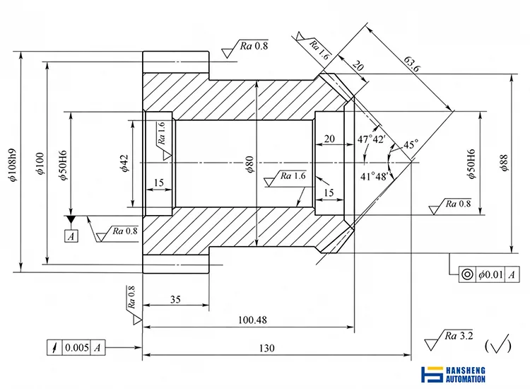
Here’s our small batch custom manufacturing case for straight bevel gear machining: 42CrMo steel, through normalizing→QT→nitriding, plus gear shaping/planing/grinding, delivers Grade 5 accuracy and φ50H6 bores at Ra0.8.
Explore our Gear Manufacturing Service for more production capabilities.
Material Selection & The 3-Stage Heat Treatment Strategy for 42CrMo Bevel Gears
Why Choose 42CrMo Steel for Straight Bevel Gear Machining?
Why 42CrMo?Its chromium and molybdenum ensure uniform hardenability, temper resistance at nitriding temperatures, and strong nitriding response for a ≥850HV case.
Three-stage thermal route:
- Normalizing (Op.20) – refines grain and removes scale before rough turning.
- Quenching & tempering (Op.40) – delivers core properties at 250–280HBW after roughing.
- Nitriding (Op.110) – hardens surface to 0.15–0.30mm case depth, ≥850HV, after gear grinding.
Why Process Order Matters for Precision Gear Machining
Order is fixed: normalize first to cut through the abrasive decarburized layer; Q&T after roughing stabilizes microstructure before finish turning; nitride after grinding teeth but before bore finishing. We leave 0.30mm grind allowance on both φ50H6 bores to absorb nitriding distortion—final bore grinding after nitriding restores concentricity to the gear pitch circle, holding Grade 5 accuracy.
Full Process Route Breakdown – From Rough Turning to Finished Bore
Phase 1: Rough Turning & Initial Reference Establishment (Op. 10–30)
| Operation | Step Summary | Key Parameters / Allowance | Equipment |
|---|---|---|---|
| 10 | Sawing stock | φ120 × 110 mm | Band saw |
| 20 | Normalising | – | Box furnace |
| 30 | Rough turning (clamp on OD with self centring chuck; face one end, leave 3 mm finish allowance; rough turn OD to φ113; drill bore to φ35; reverse, face to overall length; rough turn φ88 & φ80 ODs to φ96) | Face 3 mm finish allowance; bore drilled to φ35; ODs rough machined to φ113 / φ96 | Horizontal lathe |
Normalising homogenises the 42CrMo structure and improves machinability. Rough turning (Op.30) removes 3mm from the face—enough to clear the oxide scale and decarburised layer formed during normalising, typically 1.5–2mm deep. Cutting through this hard, brittle skin protects finishing tools and exposes clean material for later operations.
Drill the bore only to φ35—undersized, well short of final diameter. At this stage the hole serves as a chip path and a pre‑bore for quenching (Op.40). Keeping it small avoids stress concentration and reduces quench crack risk. The final bores (φ42H7 and φ50H6) are finished later, after heat treatment stabilises the material.
Phase 2: Finish Turning & Key Locating Hole Formation (Op. 50)
| Operation | Step Summary | Key Parameters / Allowance | Equipment |
|---|---|---|---|
| 50 | Finish turning (clamp on φ88 OD, then reverse and clamp on φ108h9 OD). Face ends (leave 0.10 mm grind allowance on left face). Turn φ108h9 OD to size. Turn φ42H7 bore to finished size (Ra1.6). Turn left & right φ50H6 bores, leaving 0.30 mm grind allowance. Turn cone gear OD to φ94 (taper surfaces not cut). Turn right face of gear width 35 to size. | φ42H7 finished (Ra1.6); φ50H6 bores (both ends) 0.30 mm grind allowance; gear width 35 finished; cone OD φ94 (tapers uncut) | CNC lathe |
OD Locating & Bore Differentiation Strategy
The φ108h9 OD locates the part for reverse side turning, maintaining concentricity between bore and outer diameter.Two bores are processed with distinctly different strategies at this stage:
- φ42H7 — finished directly to Ra1.6. This bore is the locating datum for gear shaping (Op.60), not an assembly feature. Finish it now to establish the shaper arbor location and eliminate subsequent handling errors.
- φ50H6 (both ends) — leave 0.30mm grind allowance. These are the final assembly bores. The undersize absorbs nitriding distortion at ~570°C. The 0.30mm stock is removed during final ID grinding (Op.120) after nitriding, bringing the bores to true size and Ra0.8.
Cone Blank Protection Strategy
On the cone gear side, rough the OD to φ94 but leave both front and rear taper surfaces completely uncut at this stage. Finish only the right face of the 35mm gear width. This protects the taper surfaces from damage or contamination during shaping (Op.60). They will be finish turned later (Op.70) with a fresh setup, using the finished bores for alignment.
Phase 3: Tooth Cutting – The “Cylindrical First” Strategy (Op. 60–80)
| Operation | Step Summary | Key Parameters / Allowance | Equipment |
|---|---|---|---|
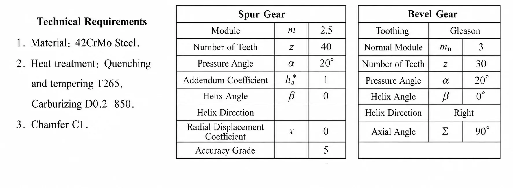
| 60 | Shape cylindrical gear (spur gear) | 0.20 mm grind allowance; located on φ42H7 bore | Gear shaper |
| 70 | Finish turn taper surfaces of bevel gear | Align to bore and right face within 0.01 mm; cut both front and rear tapers to size (Ra3.2) | CNC lathe |
| 80 | Plane bevel gear teeth to finish | mn 3, α20°, z30 | Gear planer |
Shaping (Op.60) needs a rigid locating system—the φ42H7 bore and its end face provide that. Cut the cylindrical gear first to establish a consistent datum for all subsequent operations.
Why Turn Tapers Before Planing Bevel Teeth?
Transfer the part to the CNC lathe immediately after shaping for taper turning (Op.70). Align off the finished φ42H7 bore and right end face, holding runout within 0.01mm. This cuts the tapers concentric to the same bore that later serves as the final assembly reference (φ50H6). Op.70 runs before bevel planing (Op.80)—not after.
If planing ran first, cutting forces and burrs would distort the taper surfaces and break concentricity to the bore. Turning tapers first (Op.70) on a clean, unstressed part establishes a precise reference that locates the workpiece during planing. Planing (Op.80) then cuts bevel teeth against an established taper geometry, while shaping has already fixed the cylindrical gear position relative to the shared bore.
Eliminating Setup Errors in Tooth Cutting
Shape → turn tapers → plane. Inserting a precision turning step between the two tooth‑cutting operations avoids accumulating setup errors from separate clampings. Both gear sets share the same rotational axis defined by the φ50H6 bores—a requirement for Grade 5 accuracy.
Phase 4: Final Grinding & Nitriding Sequence – The “Reverse Logic” (Op. 100–120)
| Operation | Step Summary | Key Parameters / Allowance | Equipment |
|---|---|---|---|
| 100 | Grind cylindrical gear to finish | – | Gear grinder |
| 110 | Nitriding treatment | Case depth 0.15–0.30 mm; surface hardness ≥850 HV | Nitriding furnace |
| 120 | Grind bores and end face | Grind φ50H6 bores (both ends) to finish, surface roughness Ra0.8; grind left end face to finish (Ra0.8) | Internal grinder |
Grind the cylindrical gear before nitriding (Op.100 → Op.110)—pre‑hardened teeth grind efficiently, and the nitriding cycle hardens flanks to ≥850HV without post‑grinding through the shallow case.
Grind the φ50H6 bores after nitriding (Op.110 → Op.120). The thermal cycle distorts the bores; the 0.30mm allowance from Op.50 absorbs that movement.
Final bore grinding (Op.120) removes the distorted layer, aligning off the cylindrical gear pitch circle and left end face to restore concentricity. This post‑nitriding datum recovery is what holds Grade 5.
Precision Tolerances & Alignment Strategy – Achieving Grade 5 Accuracy
A Grade 5 gear lives or dies by its datum chain. We start with the rough datum (OD) for initial chucking, transition to the φ42H7 bore as the locating datum for gear shaping (Op.60), and end with the φ50H6 bores as the final assembly reference (Op.120). Each transition transfers accuracy forward; any lost concentricity at an early stage cannot be recovered later.
Key alignment requirements from the process card:
| Operation | Alignment Reference | Tolerance |
|---|---|---|
| Op.70 (finish taper turning) | φ42H7 bore + right end face | Runout within 0.01mm |
| Op.120 (final bore grinding) | Cylindrical gear pitch circle + left end face | Concentric to gear axis |
The 0.01mm runout control on Op.70 is not optional—it ensures the taper surfaces are cut concentric to the same bore that locates the part during subsequent planing (Op.80). Without that, the bevel teeth would track eccentrically relative to the cylindrical gear.
Roughness progression tells the same story:
| Operation | Feature | Surface Finish |
|---|---|---|
| Op.50 | φ42H7 bore (locating datum) | Ra1.6 |
| Op.70 | Bevel taper surfaces | Ra3.2 |
| Op.120 | φ50H6 bores (assembly reference) | Ra0.8 |
The φ42H7 bore gets a fine turn (Ra1.6) because it must locate the shaper arbor precisely. The tapers are turned to Ra3.2—functional, not decorative. Only the final assembly bores receive the Ra0.8 grind, because that is where the shaft fits.
Across a production run, these numbers are not single-point achievements—they define repeatability. We verify every critical dimension with in-process CMM checks and supply full inspection reports with each shipment, documenting bore concentricity, runout, and surface finish against the process card tolerances.
Nitriding – The Critical Final Metallurgical Touch for High-Performance Gears
Optimizing Nitrided Case Depth Compromises
Nitriding (Op.110) sits strategically between cylindrical gear grinding (Op.100) and bore grinding (Op.120). The 0.15–0.30mm case depth is a deliberate engineering compromise: 0.15mm minimum provides sufficient wear resistance during meshing contact, while keeping depth under 0.30mm avoids core embrittlement on module 3 teeth under shock loading.
Why Bore Grinding Post-Nitriding is Non-Negotiable
At ≥850HV surface hardness, conventional carbide tools cannot cut without excessive wear and unpredictable dimensional drift. Internal grinding with vitrified CBN wheels is mandatory during Op.120 to efficiently remove distortion, maintain Ra0.8 finish, and restore pitch-circle concentricity without cracking the thin hardened case.
Tight tolerances and specific material requirements? Our engineers are ready to discuss your RFQ. Contact our technical sales team →
Capability Summary – Why This Process Matters for Your Custom Bevel Gear Orders
This process card represents a repeatable manufacturing envelope:
- Materials – 42CrMo and similar low-alloy steels (e.g. 4140, 4340) with good hardenability and nitriding response.
- Accuracy – Grade 5 per DIN 3965 (or equivalent AGMA class), verified through in-process CMM and final inspection.
- Heat treatment – Full chain: normalizing, quenching & tempering, plus nitriding with case depth 0.15–0.30mm at ≥850HV.
- Tooth cutting – Shaping (cylindrical gear) + planing (bevel teeth) + grinding (cylindrical gear finish).
Ten main operations look like a long route—and they are. But we intentionally separate the bevel taper finishing (Op.70) from the planing operation (Op.80), running tapers before cutting bevel teeth. That keeps the planer locating off a clean, unstressed taper surface, not one distorted by cutting forces or burrs from a previous setup. In small-batch production, this split protects the planer tooling and reduces fixture adjustment time between batches. We set the machine once and run the lot, without re-qualifying the taper geometry after each tooth cut.
If your application runs in higher volumes, we can adapt this sequence for automated loading—the datum scheme remains identical. For current capability or a DFM review on your specific gear geometry, contact our engineering team.
FAQ
Gear grinding must happen before nitriding—once the tooth flanks reach≥850HV, conventional grinding would strip the shallow case. Bore grinding must happen after nitriding—the thermal cycle inevitably distorts theφ50H6 bores, and the 0.30mm allowance is there to absorb that distortion before final finishing. Two hard operations sandwich the nitriding, each for a different purpose.
Theφ42H7 bore is finished during Op.50 and serves exclusively as the shaper arbor locating feature—one bore, one job, no changes. Theφ50H6 bores are left undersized until after heat treatment, then ground as the final assembly reference. Process datum and acceptance datum are separated, so we never locate a precision cutting operation off an unfinished feature.
No. Normalizing temperature, quench medium, and tempering parameters all depend on the material’s C-curve. Nitriding response is driven by Cr, Mo, and Al content—changing the alloy requires recalibrating the thermal cycle. The datum transfer logic (OD→ φ42H7→ φ50H6) and the overall sequence are reusable, but the specific temperatures and times are not.
The sequence is long, but Op.70 (finish taper turning) is positioned before planing, not after. That eliminates a second setup to re-establish taper geometry after tooth cutting, reducing fixture adjustment time and tooling wear between batches. For small lots, this order actually costs less than a“plane first, turn later”approach. Send us your drawing and batch quantity for a precise quotation.