Complete Manufacturing Process of a Precision Spline Shaft: A Real-World Drawing Case Study
Blog 2026-07-03
Using one of our real-world machining projects as a case study, this article provides a detailed walkthrough of the complete spline shaft machining process, accompanied by an in-depth engineering drawing analysis: a 45-steel shaft, quenched and tempered to 220-250 HBW, carrying a 6-key external spline centered on its major diameter.
We walk through the operation sequence the way it actually runs — where the rough turning cut stops short of finish size, where heat treatment sits in the sequence relative to turning and grinding, and why we rework the center holes twice before the final grind.
Readers looking for the broader logic behind spline types, centering methods, and design selection can refer to our earlier article, Spline Shaft Machining Processes & Design Tips.
Decoding the Technical Drawing: Dimensions, Tolerances & GD&T
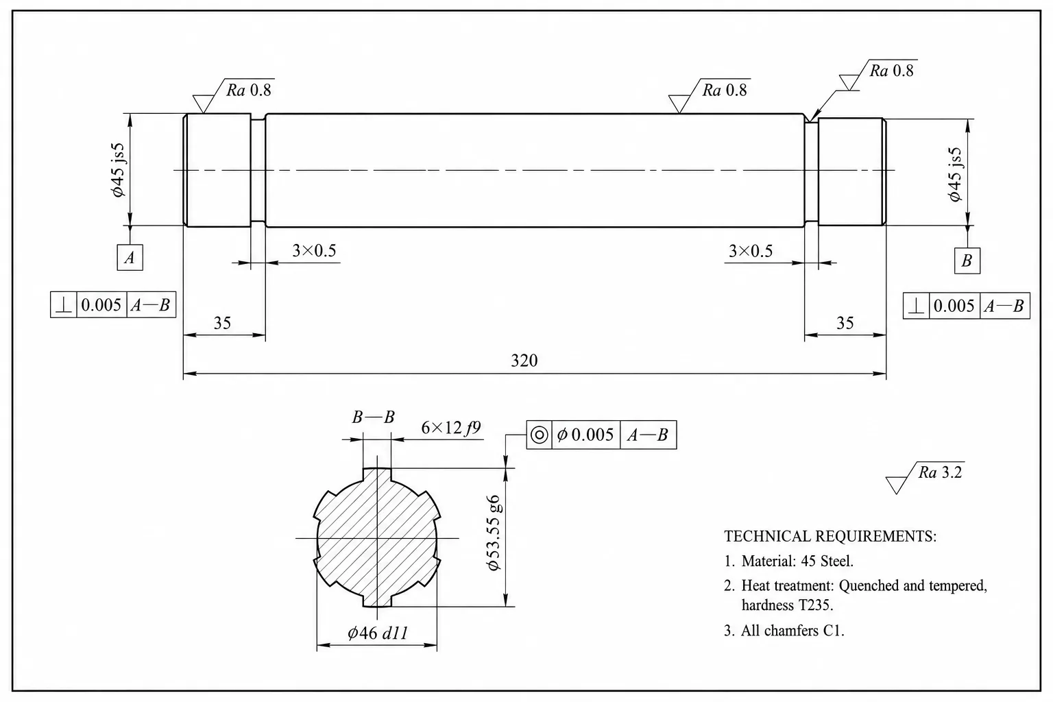
The reference drawing for this shaft carries three groups of information that shape every downstream decision: a datum structure built on two shaft journals, a major-diameter-centered spline, and a moderate quench-and-temper callout.
Geometric Dimensioning & Tolerancing (GD&T) Control
The drawing sets its datum on the common axis of the two ϕ45js5 journals (A and B) rather than on any single feature. This is a practical choice: we hold these two journals between centers from rough turning through final cylindrical grinding — they are the only surfaces that serve as the reference. Using their combined axis as datum A-B means we judge every other diameter and face against where the shaft actually sits when mounted on centers.
Three callouts stem directly from this datum:
- Coaxiality (≤0.005 mm) on the ϕ53.55g6 spline major diameter against A-B. We cannot finish this diameter by chucking — that would reference it off its own surface rather than the true rotational axis. Instead, we must grind it between the same centers used for the journals, which makes center-hole condition a controlling factor.
- Axial runout (≤0.005 mm) on the two shoulder faces adjacent to the spline. These faces typically serve as thrust or locating surfaces, so any wobble relative to A-B translates directly into misalignment at the mating part. Achieving this requires machining the faces in the same setup as the journals.
- Cylindricity (≤0.005 mm) on the journals themselves. Since these surfaces define the datum, their form error propagates into every other tolerance on the print. Holding this grade is strictly a grinding-stage requirement; turning alone cannot achieve it.
These three figures lead to one conclusion before a single chip is cut: we must locate the shaft on centers, not in a chuck, from semi-finishing through final grinding, and we must treat the center holes as precision features.
Spline Specification & Centering Type
The spline is a 6-key rectangular external type, 12f9 in width, with a ϕ53.55g6 major diameter and a ϕ46d11 minor diameter. The tolerance spread is deliberate: the major diameter carries the tightest grade (g6) because this is a major-diameter-centered spline—torque transmission and radial location both rely on that outer surface, not on the flanks or minor diameter. The key width (12f9) needs sufficient precision for engagement but nothing close to g6, while the minor diameter (d11) is loosest because it plays no locating role and only requires clearance.
This centering method dictates the process route: the major diameter is the only spline surface that receives a dedicated finishing pass. The rest of the spline profile is left as-milled, but ϕ53.55g6 is ground afterward to meet both its size tolerance and the coaxiality requirement. (A side-fit spline would shift this precision burden onto the flanks instead—a different centering type changes which surface the shop treats as critical.)
Material Chemistry & Heat Treatment Requirements
The material is 45 steel (AISI 1045 equivalent), a common medium-carbon shaft steel offering a balanced trade-off between strength and machinability without alloy additions. For a splined torque-transmitting shaft, this is a reasonable choice—there is no case-hardening or carburizing callout, only a through quench-and-temper treatment.
The hardness target of 220-250 HBW (marked T235) sits deliberately in the mid-range. Higher hardness would resist the post-heat-treatment turning and spline milling operations still required in this route; lower hardness would lack the core strength and fatigue resistance needed in service. This band is the point where the shaft is hard enough to perform, yet still soft enough to be machined cleanly with standard turning tools and a form-relieved spline cutter afterward.
The 10-Step Machining Process Sheet for the Spline Shaft
The ten operations below follow three governing rules. First, roughing and finishing are separated by heat treatment—rough cuts release stress, Q&T relieves it, and nothing is finished beforehand. Second, the two center holes drilled at the start serve as the single reference through semi-finishing, spline milling, and grinding—no re-chucking on different features. Third, heat treatment distorts even the center holes, so they are rectified after Q&T before any finish cut. These rules prevent tolerance degradation across setups and stress cycles.
Phase I: Preparation & Rough Machining (Ops 10–20)
The route starts with sawing a ϕ60×325 mm blank — stock sized well beyond the finished ϕ53.55 mm and 320 mm length to absorb facing cuts and distortion later in the route. Rough turning (Op 20) then squares both ends, drills a temporary A2.5/5.3 center hole at each end, and turns the shaft between centers: both ϕ45js5 journals are roughed to ϕ47, and the spline section is roughed to ϕ56.
II: Heat Treatment (Op 30)
This is the operation where the datum system gets rebuilt. A steady rest supports the shaft on the ϕ53.55g6 section while the faces are turned and the overall length is corrected — first to 321 mm, then to the finished 320 mm once both ends are addressed. Critically, both center holes are re-machined to A3.15/6.7 at this stage. Since heat treatment can distort the original temporary centers, grinding a fresh, accurate pair here is what makes every downstream operation trustworthy — without it, the final grinding pass would simply inherit whatever error the centers picked up in the furnace.
With the centers rectified, we finish-turn the shaft between double centers: we cut both ϕ45js5 journals and the ϕ53.55g6 major diameter to within 0.25 mm of final size, leaving that allowance for grinding, while we leave the adjacent shoulder faces with a 0.10 mm facing allowance. We cut the 3×0.5 relief grooves to final size and chamfer all outer edges to C1.
IV: Spline Cutting & Deburring (Ops 50–60)
We mill the 6×12f9 external rectangular spline in one operation, on a vertical machining center fitted with a form spline milling cutter — the same role a dedicated spline shaft milling machine would fill in a higher-volume shop. Because the major diameter still carries its grinding allowance at this point, the spline cutter only needs to hold the tooth profile and key width; it is not responsible for the final size or finish on ϕ53.55g6.
Bench work (Op 60) follows immediately, removing burrs off the spline teeth and shoulder edges.
V: Precision Grinding & GD&T Realization (Ops 70–80)
Before grinding, we polish the center holes again (Op 70) on a center-hole grinder — a second, finer pass on top of the rectification we performed in Op 40, aimed purely at sharpening the positioning datum ahead of final grinding.
Cylindrical grinding (Op 80) is where the tolerances called out on the drawing are actually delivered. Working between double centers, the grinder finishes both ϕ45js5 journals and their adjacent shoulder faces to Ra 0.8 μm, then grinds the ϕ53.55g6 spline major diameter to the same finish.
VI: Metrology Inspection & Packaging (Ops 90–100)
Final inspection (Op 90) checks all dimensions along with the coaxiality, circular runout, and cylindricity call-outs, using calipers, micrometers, and a runout tester alongside a roughness gauge to confirm the Ra 0.8 μm finish. Once the part clears inspection, it’s coated with rust-preventive oil, packaged, and moved into storage (Op 100).
Process Summary Table
Critical Challenges & Manufacturing Tips for Engineers
How to Prevent Spline Distortion After Q&T?
Quenching a slender shaft induces some bow—normal, but manageable. The mitigation must be set before rough turning: leave sufficient stock on all diameters, and re-machine the center holes after Q&T rather than reusing the original ones. A shaft roughed too close to final size leaves the straightening and re-centering operations no material to correct, and any residual bow becomes locked into the finished journals.
Maintaining Coaxiality with Combined Datum A-B
Achieving 0.005 mm coaxiality against A-B is not about chucking accuracy—it requires grinding between the same two centers used for all previous operations. A chuck introduces its own runout; centers locate the shaft on its true rotational axis. This makes center-hole condition the single most critical factor: any wear or out-of-roundness on the centers transfers directly into coaxiality error on the finished major diameter, regardless of wheel precision.
Controlling Surface Integrity on Centering Diameters
Reaching Ra 0.8 μm on ϕ53.55g6 without thermal damage is a feed-and-wheel selection problem, not a machine-rigidity issue. Excessive feed rate or a wheel grade too hard for 45 steel raises local grinding temperatures enough to alter surface metallurgy—a defect undetectable by roughness gauging but visible as premature service wear. On a centering diameter, surface integrity directly affects both the interference fit and the long-term stability of the coaxiality it was ground to maintain.
Conclusion & Custom Spline Shaft Manufacturing Capabilities
Nothing in this process sheet is exotic on its own — rough turning, quench and temper, milling, grinding. What holds the 0.005 mm coaxiality together is sequencing: leaving stock where it’s needed, rectifying the center holes after heat treatment, and never departing from the A-B datum once it’s established. That discipline, more than any single machine, is what separates a compliant spline shaft from a scrapped one.
Our shop runs this same logic on spline and gear shaft work day to day — precision spline shaft milling machines, CNC cylindrical grinders, and full metrology coverage for coaxiality, runout, and surface finish verification. We machine to DIN 5463, ISO 14, ANSI B92.1, and non-standard drawings alike, including micron-level tolerance callouts like the one reviewed here.
If you have a spline shaft drawing to quote, send it through for an RFQ and we’ll review the tolerance stack and process route directly with you.
FAQ
For low-to-mid volume production, a vertical machining center fitted with a form spline milling cutter—as used in this process sheet—is the common choice. Higher-volume shops often move to a dedicated spline shaft milling machine or a hobbing setup, which cuts the full tooth profile in fewer passes but requires higher tooling investment upfront.
We mill the spline while the major diameter still carries its grinding allowance, so the cutter only has to hold the tooth profile and key width — not the final size or coaxiality. Grinding afterward brings the major diameter to Ra 0.8 μm and its final tolerance in one pass, and we reference it off the same centers used throughout the route, rather than asking the spline cutter to hold a precision it isn’t set up to deliver.
Only where the drawing calls for coaxiality or runout tolerances in the same range as this one (0.005 mm against a combined datum). Shafts with looser positional tolerances can often be finished with standard chucking and fewer re-centering steps. The tighter the callout, the more the process depends on the center holes as the single source of truth for location.
Major-diameter centering, as used on this shaft, puts the precision and grinding effort on the outer diameter (ϕ53.55g6 here), leaving the flanks as-milled. Side-fit centering shifts that same precision requirement onto the spline flanks instead, which typically calls for a different finishing method—flank grinding rather than a straightforward cylindrical grind on the OD.