Rectangular Spline Sleeve Manufacturing Process: Material, Machining, Broaching & Quality Control
Blog 2026-07-15
Rectangular spline sleeve manufacturing (ISO 14) produces internal straight-sided splines for torque transmission. Key steps include forging, normalizing, rough machining, quenching and tempering, precision turning, and broaching. Critical challenges are achieving the spline profile while controlling bore-to-spline concentricity, datum consistency, and heat-treatment distortion. Success relies on material selection (e.g., 45 steel), stress management, and functional inspection using gauges and precision metrology.
Drawing on actual in-house machining cases, this article explores topics such as drawing analysis, material selection, process workflows, and quality control at Hansheng Automation.
Interested in learning about the corresponding rectangular spline shaft manufacturing?
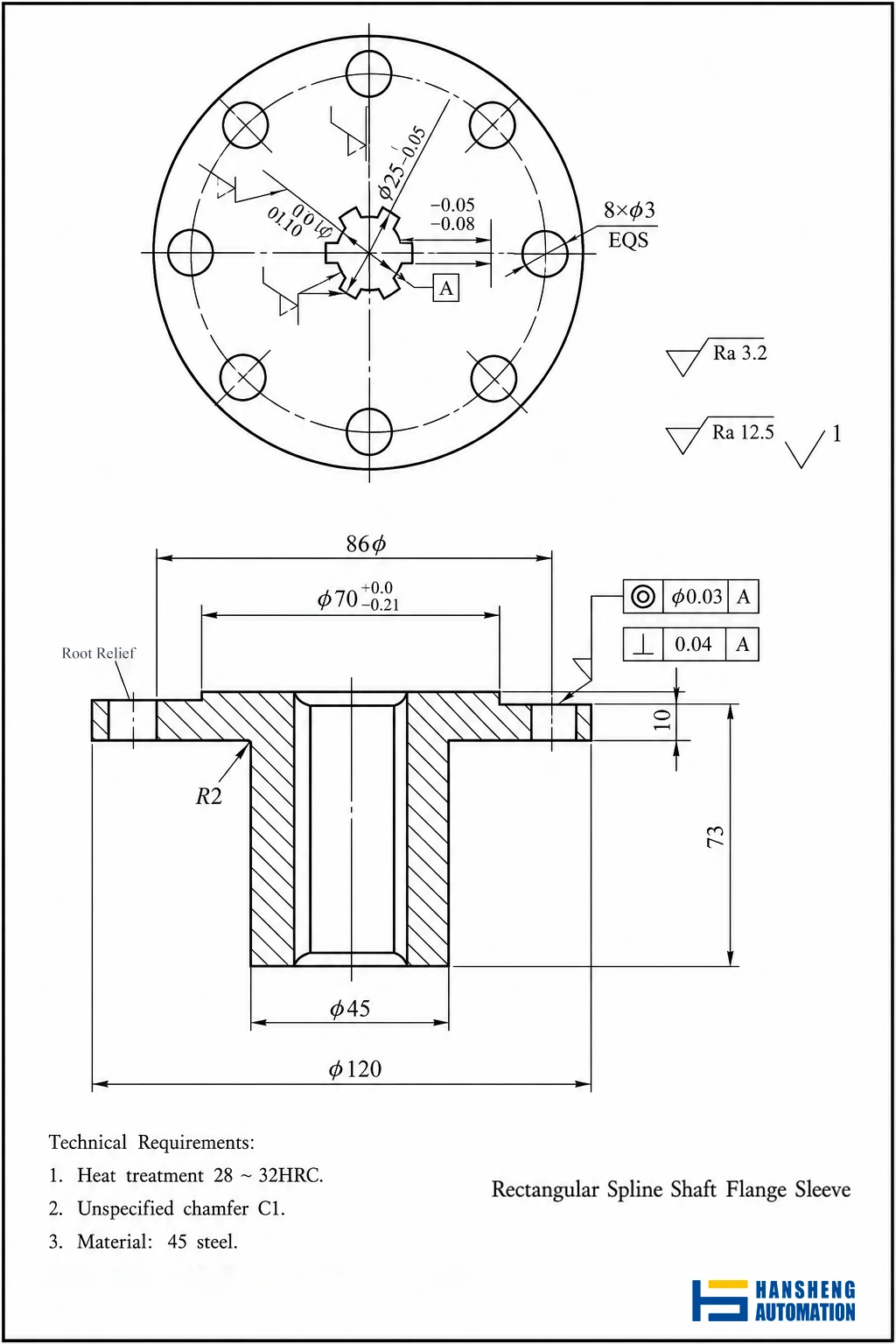
Drawing Analysis of a Rectangular Spline Sleeve: Critical Dimensions and Tolerance Requirements
Material Selection: Why 45 Steel(AISI 1045) is Used
Selecting the appropriate material for a transmission component requires balancing mechanical performance, manufacturability, and cost. For this rectangular spline sleeve, 45 steel (a medium carbon steel, equivalent to AISI 1045) is selected as the primary material. It provides excellent machinability, sufficient fatigue strength, and highly responsive quenching and tempering characteristics.
The structural geometry of this specific part presents manufacturing challenge: a substantial diameter transition between the positioning flange (ϕ120mm) and the main body (ϕ45mm). Forging this abrupt stepped profile demands a relatively large forging ratio to ensure proper material flow and grain refinement. However, high forging ratios inevitably introduce severe, uneven internal stresses and directional grain structures. To ensure a uniform microstructure and minimize distortion, a systematic heat treatment process is essential, particularly normalizing after forging followed by quenching and tempering (Q&T).
From a shop-floor perspective, while 45 steel is highly forgiving during rough turning, controlling residual stress prior to final machining is paramount. Neglecting intermediate stress relief or failing to monitor tool wear during roughing can lead to micro-deformation during subsequent heat treatment. This deformation can easily warp the part enough to consume the entire finish-machining allowance, resulting in scrapped parts.
Critical Dimensions and GD&T Requirements for Rectangular Spline Sleeves
To guarantee the functional performance of the spline sleeve under dynamic load, several key dimensions and geometric tolerances must be strictly controlled during the machining cycle:
| Feature | Requirement | Manufacturing Purpose |
|---|---|---|
| Locating reference diameter (OD) | ϕ70±0.021mm | Ensure accurate workpiece positioning during broaching |
| Coaxiality | 0.03mm | Prevent eccentric loading |
| End face perpendicularity | 0.04mm | Ensure assembly accuracy |
| Hardness | 28-32 HRC | Balance strength and toughness |
How Datum Selection Affects Spline Machining Accuracy
In actual shop production, these geometric tolerances (GD&T) regularly prove far more challenging to maintain than standard linear dimensions. Even when all turned diameters fall well within their respective limits, minor errors in datum selection during the turning stage can propagate. When the part is transferred to the broaching machine, the workpiece is located using the reference outer diameter (φ70±0.021mm) and the right end face of the φ120mm flange. Any slight runout or deviation in these locating surfaces will lead to severe accumulated coaxiality errors in the finished spline profile. Thus, establishing a consistent machining datum from start to finish is non-negotiable.
Rectangular Spline Sleeve Manufacturing Process: From Forging to Internal Spline Broaching
1: Forging and Normalizing of the Spline Sleeve Blank
The manufacturing process begins by cutting the 45 steel bar stock to length, followed by hot forging to produce the stepped blank. Immediately after forging, the workpiece undergoes normalizing before any machining operation.
Manufacturing Challenge
The large diameter transition in the forging can lead to uneven metal flow and significant residual stresses. If these stresses are not relieved, distortion may occur during later machining and heat treatment.We perform normalizing immediately after forging to homogenize the microstructure and reduce internal stresses before rough machining begins.
We perform normalizing immediately after forging to homogenize the microstructure and reduce internal stresses before rough machining begins.
2: Rough Machining and Stress Control
Rough machining removes the majority of the forging allowance through turning, facing, and drilling while establishing reliable datum surfaces for subsequent operations. Removing excess material at this stage improves machining efficiency while preparing accurate reference surfaces for precision machining.
Manufacturing Challenge
Aggressive material removal or unbalanced cutting can release residual stresses unevenly, increasing the risk of deformation during heat treatment.Solution: Rather than maximizing material removal in a single pass, we leave a balanced machining allowance and use controlled cutting parameters to minimize stress redistribution.
Solution: Rather than maximizing material removal in a single pass, we leave a balanced machining allowance and use controlled cutting parameters to minimize stress redistribution.
3: Quenching and Tempering (Q&T)
After rough machining, the workpiece undergoes quenching and tempering to achieve the required hardness of 28–32 HRC while improving strength and toughness. Performing Q&T after rough machining minimizes dimensional changes during finish machining and provides the required mechanical properties for service.
Manufacturing Challenge
Hardness variation across the workpiece is often more problematic than hardness itself. Localized hard spots can produce unstable cutting forces during finish turning.Solution: In addition to verifying hardness values, we monitor hardness uniformity to ensure stable machining behavior and consistent dimensional accuracy.
Solution: In addition to verifying hardness values, we monitor hardness uniformity to ensure stable machining behavior and consistent dimensional accuracy.
4: Precision Turning and Datum Preparation
Precision turning finishes the critical locating features that will guide every subsequent operation. The outer diameter (φ70±0.021mm) and the right end face of the φ120mm flange are machined to their final dimensions and geometric tolerances. These two surfaces together establish the primary datum that will locate the workpiece during broaching—the single most important setup decision in the entire manufacturing sequence.
Why does this matter? The broach follows the axis defined by these locating surfaces. If the φ70 outer diameter is machined with even 0.01mm of taper, or if the end face is not perfectly perpendicular to the axis, that error will be transferred directly to the spline profile. There is no opportunity to correct it later.
Additionally, the inner bore is precision-bored to φ19+0.10 mm. This hole is not used for locating during broaching—it serves a different purpose: it is the mounting hole for an inspection mandrel. During post-machining quality verification, a precision-ground mandrel is inserted into this bore, and the assembly is mounted on a deflection tester to check coaxiality and perpendicularity against the reference surfaces.
How We Control Datum Accuracy
To ensure the locating features are machined correctly, we apply several controls during this step:
- First, rough machining is performed before heat treatment, so the precision turning operation removes only a thin, uniform finishing allowance. This minimizes cutting-induced stress and preserves the dimensional stability achieved by quenching and tempering.
- Second, all finish turning operations reference the same locating surfaces throughout the setup. Once the φ70 outer diameter and the φ120 end face are machined, they become the non-negotiable reference for all subsequent cuts on the same workpiece. We do not change the locating strategy between operations.Third, rigid fixturing is used to minimize clamping-induced errors. The workpiece is held securely but without over-constraint, ensuring that the locating surfaces remain undistorted during cutting.
5: Internal Rectangular Spline Broaching
The internal rectangular spline is produced in a single pass using a precision broaching tool. Broaching provides excellent profile consistency, indexing accuracy, and production efficiency for internal spline manufacturing.
Manufacturing Challenge
Even slight deviations in the locating reference surfaces (the φ70±0.021mm outer diameter and the φ120mm end face) can cause misalignment during broaching, resulting in spline runout or profile errors. The broach is guided by the workpiece’s own reference features, so any imperfection in these surfaces directly affects spline accuracy.
How We Control It
The locating reference diameter and end face are carefully finished and verified before broaching. The workpiece is fixtured using these surfaces to ensure consistent alignment. The finished spline is then inspected using functional GO/NO-GO spline gauges together with periodic CMM verification.
6: Radial Drilling and Deburring
With the spline profile complete, the part is transferred to a drill press, where eight radial holes of ϕ13mm are drilled and equally distributed. Afterward, a thorough manual bench-deburring process is carried out. This ensures that both the internal spline teeth and the drilled hole ports are completely free of burrs or sharp edges, guaranteeing seamless final assembly and proper preparation for warehousing.
Quality Control and Inspection Methods for Rectangular Spline Sleeves
Given the high-torque, reversing-load environments these components operate in, geometric deviations must be strictly controlled to prevent failure. To ensure compliance with engineering prints, our workshop implements a multi-tiered quality control system. The complete quality inspection system integrates dedicated, specialized fixtures with universal measuring equipment to inspect every critical feature of the rectangular spline sleeve:
- Coaxiality and Perpendicularity Verification: Rather than relying solely on time-consuming coordinate measuring machine (CMM) routines for standard setups, we utilize a deflection tester paired with high-sensitivity dial indicators on the shop floor.
- Spline Profile and Indexing Inspection: We employ custom-designed comprehensive spline plug gauges to quickly inspect the spline’s tooth width, major/minor diameters, and indexing accuracy in a single functional step.
- Dimensional Metrology and Laboratory Auditing: These specialized methods are integrated with universal measuring tools, including coordinate measuring machines (CMMs) for complex geometric validation, external micrometers for precision outer-diameter verification, dial bore gauges for measuring pilot bore diameters, and digital height gauges for verifying overall length and flange thicknesses.
FAQ
A rectangular (or straight-sided) spline sleeve is a cylindrical mechanical coupling with internal, parallel-sided keyways. Governed by standards such as ISO 14 [1.1.9, 1.2.9], it mates with a matching external splined shaft to transmit high rotational torque while allowing axial sliding movement along the shaft axis when required.
Broaching is the preferred method for cutting internal rectangular splines because it generates the entire multi-tooth profile in a single pass. This provides unmatched productivity in production runs, exceptional indexing (angular spacing) accuracy, and a superior surface finish that remains highly consistent across large batches.
Medium carbon steels like 45 steel (AISI 1045) are the most common choice for general power transmission due to their excellent machinability and predictable response to quenching and tempering (Q&T). For high-wear, high-load, or heavy-shock environments, medium-carbon alloy steels (such as AISI 4140) or case-hardening steels (such as AISI 8620 or 20CrMnTi) are selected.
Use the finish-turned OD (φ70±0.021mm) and flange face as the unified datum for final turning and broaching. For inspection, insert a mandrel into the φ19+0.10 bore, measure runout against datum surfaces with dial indicators, ensuring coaxiality ≤0.03mm and perpendicularity ≤0.04mm.
Using precision turning and quality-controlled broaching, typical industrial setups achieve reference locating diameter tolerances within IT7 or IT8 grade limits. Geometric tolerances, including coaxiality of the spline axis to the reference locating diameter (φ70±0.021mm) and the perpendicularity of the datum face (φ120mm end face), are reliably held between 0.02mm and 0.04mm when proper datum consistency is maintained throughout the process.
Conclusion
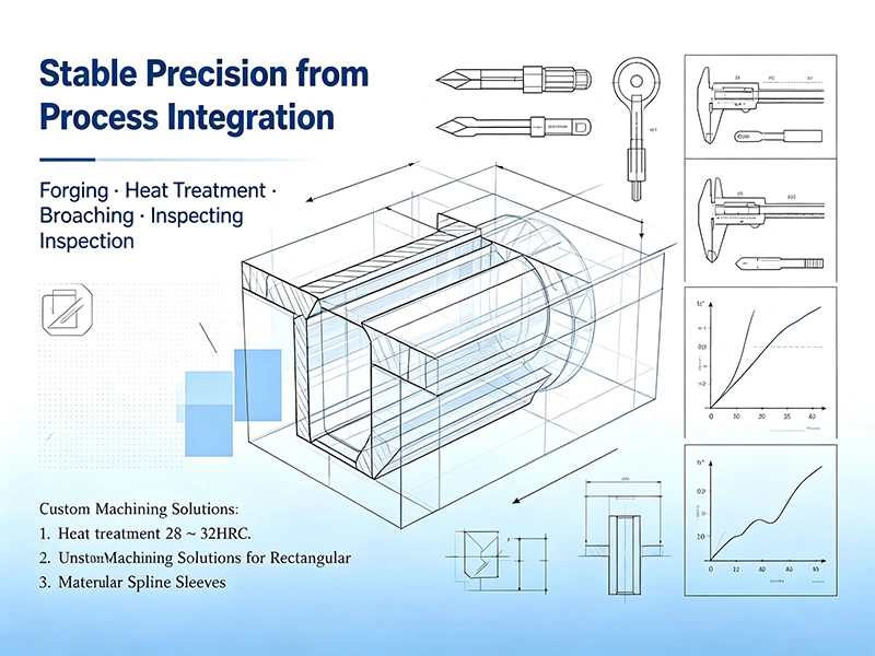
Although the machining sequence of a rectangular spline sleeve may appear straightforward, achieving stable spline accuracy depends on the integration of every manufacturing stage rather than on any single process. Controlled forging, optimized heat treatment, consistent datum management, precision broaching, and rigorous inspection all contribute to the final dimensional accuracy and long-term reliability of the component.
True manufacturing capability is reflected in how process stability is maintained, how distortion is controlled throughout production, and how critical tolerances are consistently verified before delivery.
If you require custom rectangular spline sleeve machining, Hansheng engineering team can assist with drawing review, material selection, process optimization, and precision manufacturing. From prototype development to volume production, we provide complete machining solutions backed by rigorous quality control and practical manufacturing experience.