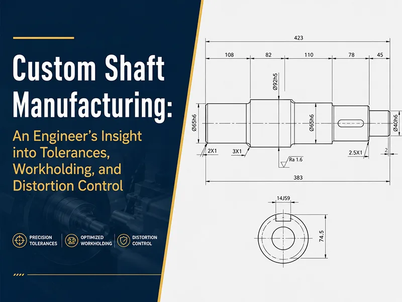
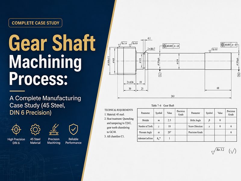
How to Machine Spline Shafts: Manufacturing Processes, Process Selection, and Design Tips
Blog 2026-06-30
Spline shaft failures rarely trace back to bad material — they trace back to a process decision made too early, without enough information. The wrong machining process for a given tolerance class, or a heat treatment sequence that wasn’t accounted for at the design stage, can quietly push a shaft out of spec before it ships.
This article walks through the main spline shaft manufacturing processes, when to use each one, and the design and tolerance decisions that determine not only if your finished shaft matches the drawing, but if it can be produced reliably and cost-effectively.
What Is a Spline Shaft
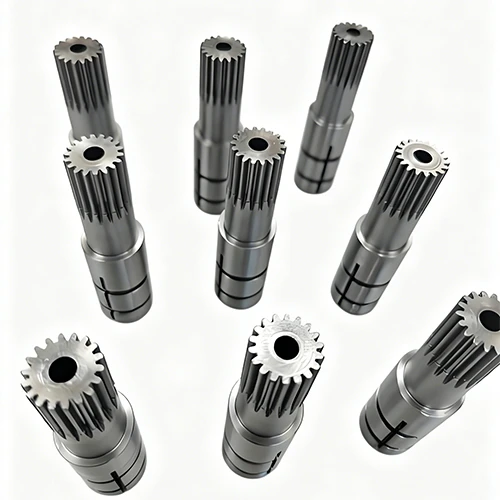
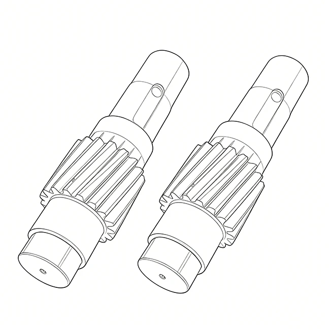
A spline shaft is a shaft with a series of ridges or teeth machined along its length, designed to mesh with a matching internal profile to transmit torque. Unlike a keyed shaft — which relies on a single key and keyway — a spline distributes load across multiple teeth simultaneously, which changes the mechanical behavior in ways that matter at the design stage.
Spline Shaft vs. Keyed Shaft
| Metric | Spline Shaft | Keyed Shaft |
|---|---|---|
| Load contact area | Distributed across all teeth | Single key face |
| Torque capacity | Higher for the same shaft diameter | Lower |
| Fatigue life | Better under cyclic or reversing loads | More sensitive to stress concentration at keyway |
| Axial sliding | Possible (sliding fit) | Not practical |
| Machining complexity | Higher | Lower |
The practical implication: Designers specify splines for high-torque, reversing-load, or axially-sliding applications — such as transmission shafts, driveline components, and machine tool spindles.
External vs. Internal Splines
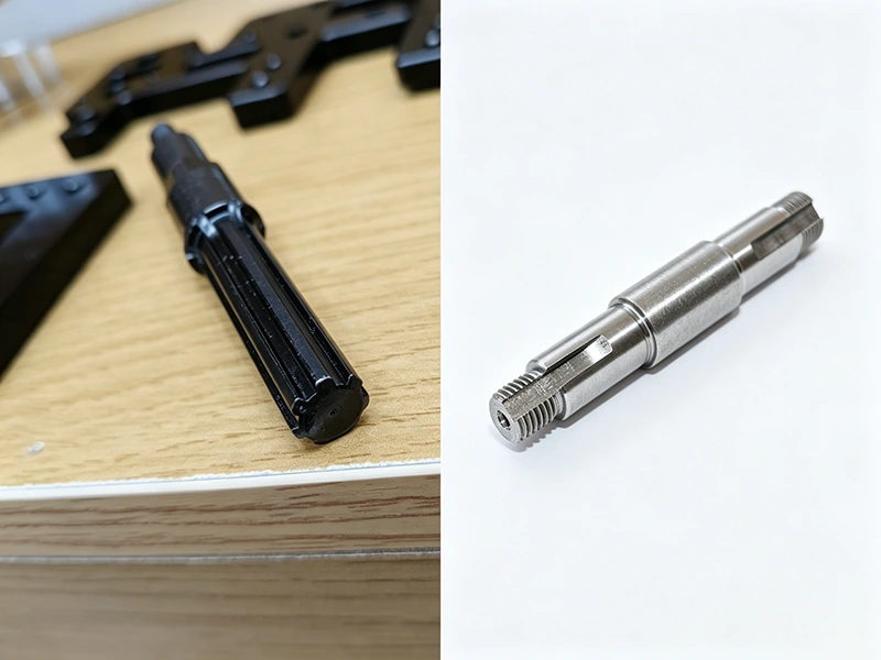
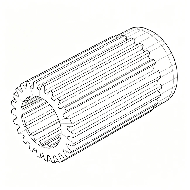
External splines are machined on the outer surface of a shaft and are the more common form — most hobbing and milling operations produce external profiles. Internal splines are cut into the bore of a hub or sleeve, and typically require broaching or shaping. In an assembly, the two always appear as a matched pair; the process selected for each half is often different.
Types of Spline Profiles
Spline profile selection affects which machining processes are available, what tolerances are achievable, and how the joint behaves under load.
Spline Shaft Geometry: Key Parameters
Before selecting a machining process, the spline geometry should be fully defined. The main parameters include:
| Parameter | Function |
|---|---|
| Number of teeth (z) | Determines the number of spline teeth |
| Module (m) or diametral pitch | Defines the basic tooth size |
| Pressure angle | Defines tooth flank geometry |
| Pitch diameter | Reference diameter for the spline profile |
| Major diameter | Outside diameter of an external spline |
| Minor diameter | Root diameter of an external spline |
| Tooth thickness | Influences fit and backlash |
| Spline length | Determines axial engagement length |
| Root radius | Influences tooth-root stress concentration |
| Fit class | Defines the required clearance or fixed fit |
| Centering method | Defines how the shaft and hub are located relative to each other |
For a metric involute spline, the nominal pitch diameter can be expressed in simplified form as:
For example, a spline with a module of 2 mm and 20 teeth has a nominal pitch diameter of approximately 40 mm.
Module and tooth count alone are not sufficient to define a manufacturable spline. The applicable standard, pressure angle, fit, centering method, and inspection requirements must also be established.
Parallel (Straight-Sided) Splines
Flat flanks, simple to inspect. Centering relies on major or minor diameter rather than the tooth form, which limits load distribution and increases root stress concentration. Primarily found in legacy designs and low-speed heavy-load applications.
Involute Spline Machining
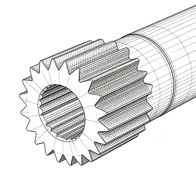
The preferred choice for many new spline designs because of their standardized geometry, broad tooling availability, and predictable fit and inspection methods. Pressure angle should be selected according to the applicable spline standard. A 30° pressure angle is widely used in industrial applications, while ISO 4156 also defines 37.5° and 45° pressure-angle systems.
Common standards include:
- ISO 4156 — International metric involute splines
- DIN 5480 — European industrial applications
- SAE J498 — North American automotive and off-highway applications
The applicable standard, pressure angle, fit system, and centering method should be specified before machining.
Serrated Splines
Triangular tooth form, high tooth count, typically used on shafts under 50mm. Suitable for light loads and angular positioning (e.g. steering columns). Not appropriate where significant reversing torque is present.
Helical Splines
Axial movement produces a controlled angular displacement. Used in specific actuator mechanisms. Machining complexity is higher; not a general-purpose profile.
Crowned Splines
A convex modification along the tooth length accommodates angular misalignment — typically 1–3° — without edge loading. Applied during grinding or a controlled hobbing pass. Common in driveshafts and flexible couplings.
Profile Selection Matrix
| Profile | Typical Application | Main Advantage | Main Limitation | Typical Manufacturing Consideration |
|---|---|---|---|---|
| Parallel / Straight-Sided | Legacy machinery, heavy-duty applications | Simple geometry | Limited centering capability | Shaping, milling, broaching |
| Involute | Power transmission, automotive, industrial machinery | Standardized geometry and good load distribution | Requires controlled profile and fit | Hobbing, shaping, broaching, grinding |
| Serrated | Steering and positioning applications | High tooth count and compact geometry | Less suitable for high reversing torque | Broaching, shaping, milling |
| Helical | Specialized actuators and engagement systems | Axial movement can produce angular displacement | More complex manufacturing | Specialized hobbing or shaping |
| Crowned | Drivelines and flexible couplings | Better accommodation of angular misalignment | More demanding tooth modification | Controlled grinding or finishing |
Spline Shaft Manufacturing Processes
No single process covers all spline shaft geometries, volumes, and tolerance requirements. The table below maps the main options across the dimensions that matter for process selection — use it as a starting point before the detailed breakdown.
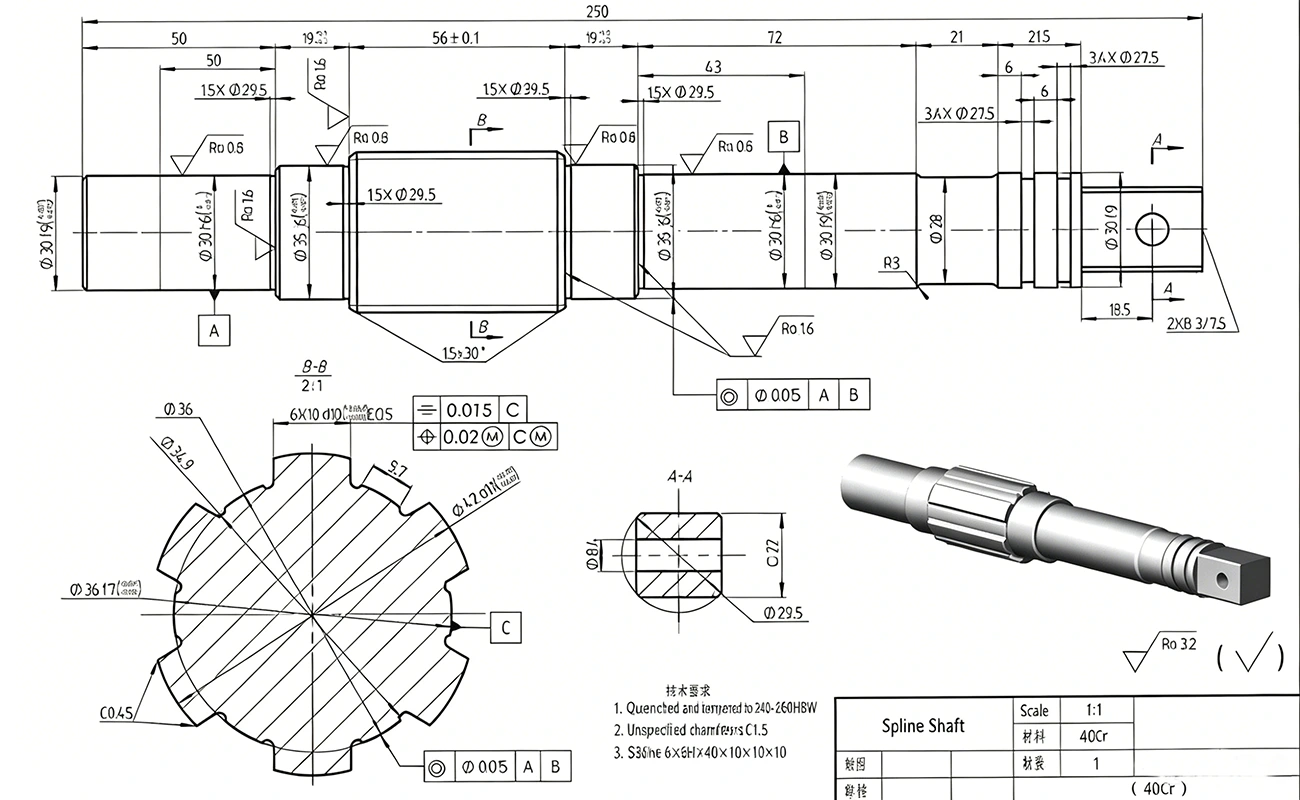
Tip for Engineers: View the full case study: A complete 10-step analysis of spline shaft machining based on real engineering drawings.
| Process | Spline Type | Volume | Tolerance | Setup Cost | Speed |
|---|---|---|---|---|---|
| Hobbing | External, Involute | High | IT6–IT8 | Medium | Fast |
| Broaching | Internal, External | Medium–High | IT5–IT7 | High (tooling) | Very Fast |
| CNC Milling | All types | Low–Medium | IT7–IT9 | Low | Slow |
| Gear Shaping | Internal & External | Low–Medium | IT6–IT8 | Medium | Medium |
| Grinding | Post-HT correction | Any | IT4–IT6 | High | Slow |
| Hard Skiving | Internal & External | Medium | IT5–IT7 | Medium | Fast |
Spline Hobbing Process
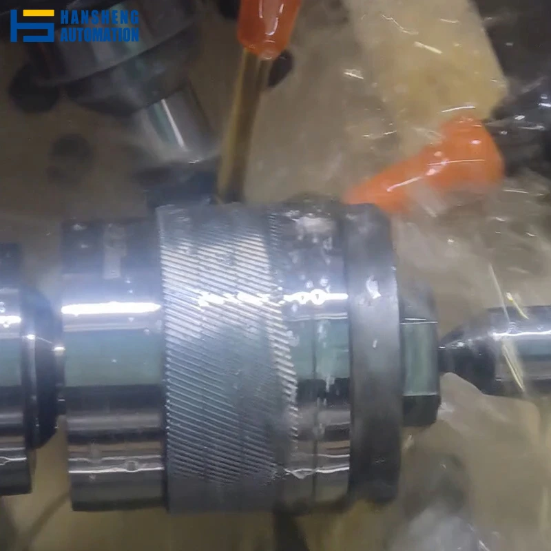
A hob is a cylindrical cutting tool with helically arranged teeth; it rotates in a synchronized relationship with the workpiece to generate the spline profile through a continuous generating cut. In production, this means the entire external spline is formed in a single pass without indexing — which is why hobbing is the standard process for high-volume external involute splines.
Typical cutting speeds run 80–150 m/min for alloy steel with carbide hobs; axial feed per workpiece revolution is usually set in the range of 1–3mm depending on module and finish requirements. Under suitable machine, tooling, workholding, and process conditions, hobbing can achieve a relatively high level of dimensional and profile accuracy on standard involute splines. The final achievable tolerance should be established from the actual drawing, machine capability, material, and inspection requirements rather than assigned to a fixed IT range.
One hard boundary: hobbing cannot produce internal splines. If the design calls for an internal profile, a different process is required from the outset.
Broaching — Internal vs External Spline Machining
Linear broaching pushes or pulls a multi-tooth tool through a bore in a single stroke, with each successive tooth removing a small increment of material. The result is a finished internal spline in one pass — cycle times under 30 seconds are common in production. Rotary broaching uses a similar principle on CNC lathes or machining centers, making it practical for external splines and smaller internal profiles without a dedicated broaching machine.
The trade-off is tooling cost: a broach is a precision tool ground to a specific profile, and custom profiles can run $3,000–$8,000 or more per tool. At volumes above a few hundred pieces, the per-part cost drops quickly. Below that threshold, the tooling investment is harder to justify.
CNC broaching on machining centers has expanded access to the process — shops without dedicated broaching equipment can now run internal spline profiles using rotating broach holders, which is worth specifying when sourcing lower-volume internal spline work.
Gear Shaping & CNC Milling
CNC Milling generates spline teeth by indexing the workpiece and cutting each tooth space individually with an end mill or form cutter. Setup requires no dedicated tooling beyond standard cutters, which makes it the practical choice for prototypes, non-standard profiles, and small runs where broach or hob tooling isn’t justified. On a 5-axis machine, complex geometries — tapered splines, shafts with interrupted features near the spline — are accessible without multiple setups. The limitation is cycle time: milling is significantly slower than hobbing or broaching, and surface finish on the flanks typically requires a follow-up operation for fits tighter than IT7.
Gear Shaping uses a reciprocating gear-shaped cutter that generates the profile through a rotary generating motion. Unlike hobbing, it can produce both internal and external splines, and it can work closer to shoulders or adjacent features where a hob’s runout would interfere. In practice, shaping is the go-to process for internal splines when broaching tooling isn’t available, and for external splines on shafts with limited axial clearance. Tolerance capability sits at IT6–IT8 under normal conditions.
Grinding & Hard Skiving — Post-Heat-Treatment Correction
Heat treatment — whether carburizing, nitriding, or induction hardening — introduces dimensional change. On involute splines, pitch diameter drift and tooth form distortion after quenching are expected; the question is how much, and whether it pushes the part outside tolerance.
Two situations often require evaluation of a post-heat-treatment correction process:
- The final hardness is high enough that conventional cutting is no longer practical.
- The final dimensional or profile tolerance is tight enough that expected heat-treatment distortion could consume the available tolerance band.
Whether grinding, hard skiving, or another finishing process is required should be determined from the material, heat-treatment method, spline geometry, distortion level, and final drawing requirements.
Hard skiving is an alternative that has seen increasing adoption in the last decade. A skiving cutter — similar in principle to a gear skiving tool — operates at a crossed-axis angle to the workpiece and generates the profile through a continuous rotary cutting motion. On hardened material (up to ~62 HRC with coated carbide tooling), hard skiving can achieve IT5–IT7 at significantly faster cycle times than grinding, and it handles internal splines — a geometry where grinding is mechanically difficult. It is not yet as widely available as grinding, but for medium-volume internal splines requiring post-HT correction, it’s worth evaluating in your supply chain.
Process Selection Framework
| Design / Production Condition | Process to Consider | Main Reason |
|---|---|---|
| Standard external involute spline | Hobbing | Efficient generating process |
| Standard internal spline, high production volume | Broaching | Very short cycle time after tooling investment |
| Low-volume or prototype spline | CNC Milling / Shaping | Lower tooling investment |
| Internal spline without broach tooling | Shaping / Skiving | Flexible internal-profile production |
| Complex spline geometry or restricted shoulder access | Milling / Shaping | Better tool accessibility |
| Tight post-heat-treatment tolerance | Grinding / Hard Finishing | Corrects heat-treatment distortion |
| Hardened internal spline, medium volume | Consider Hard Skiving | Suitable for internal hard finishing when applicable |
The decision is rarely one-dimensional. The decision should consider spline type, profile standard, part size, production volume, tolerance requirements, material, heat treatment, tooling availability, and final inspection requirements. Production volume is important, but it should not be used as the sole process-selection criterion.
Material Selection for Spline Shafts
Material choice for a spline shaft is rarely made in isolation — it directly constrains which machining processes are viable and what heat treatment options are available downstream.
| Material | Typical Grade | Strength | Machinability | Application |
|---|---|---|---|---|
| Alloy Steel | 4140, 4340 | High | Good | Automotive, industrial machinery |
| Stainless Steel | 303, 316 | Medium | Fair | Corrosive environments |
| Aluminum | 6061, 7075 | LowMedium | Excellent | Lightweight, aerospace |
| Titanium | Grade 5 (Ti6Al4V) | High | Poor | Aerospace, medical |
| Casehardening Steel | 8620, 9310 | Very High | Good | Highfatigue, carburized applications |
process compatibility and Material is where decisions get constrained in practice:
Steels for High-Torque Power Transmission
- 4140 / 4340 machine well at hobbing speeds and respond predictably to through-hardening or induction hardening — the most straightforward combination for general industrial splines.
- 8620 / 9310 are specifically designed for carburizing; the low core carbon keeps the core tough while the case reaches 58–62 HRC. Post-carburizing distortion on spline teeth is expected and should be accounted for with grinding stock at the design stage.
Specialty Materials: Corrosion Resistance & Lightweight Alloys
- Stainless steels (303, 316) can be hobbed or shaped, but work-hardening during cutting requires lower speeds and positive-rake tooling. Common austenitic stainless steels such as 303 and 316 cannot be hardened through conventional quench-and-temper treatment. Their machinability and surface-hardening options therefore differ from alloy steels commonly used for power-transmission splines. Where additional wear resistance is required, the appropriate surface treatment should be selected based on the specific stainless grade and service conditions.
- Aluminum alloys such as 6061 and 7075 are readily machinable and are often produced by CNC milling, shaping, or other suitable cutting processes for lower-volume spline work. Hobbing can be more challenging because built-up edge, chip evacuation, tooling geometry, and cutting parameters must be carefully controlled, particularly at aggressive production conditions.
- Titanium Grade 5 requires slow cutting speeds, sharp tooling, and careful chip management regardless of process. Hobbing titanium splines is possible but uncommon; CNC milling with coated carbide at conservative parameters is more typical. No conventional case hardening applies — anodizing or nitriding are the surface treatment options if needed.
In most power transmission applications, alloy steel (4140 or 4340) or case-hardening steel (8620 or 9310) covers the requirement. Material substitutions driven by weight or corrosion requirements should be evaluated against the process and heat treatment implications before the drawing is finalized.
Heat Treatment and Distortion Control
Surface hardening is standard practice for spline shafts in load-bearing applications — but heat treatment introduces dimensional change, and on a spline profile, that change is rarely uniform.
Process Selection: Carburizing, Nitriding, and Induction Hardening
Carburizing diffuses carbon into a low-carbon steel surface (typically 8620 or 9310) before quenching, producing a hard case of 58–62 HRC with a tough core. Case depth typically runs 0.5–1.5mm depending on load requirements. The quench step introduces the most distortion of the three processes — a post-HT correction pass is usually necessary for splines at IT6 or tighter.
Nitriding operates at lower temperatures (500–570°C) without a quench, which means significantly less distortion. Surface hardness reaches 58–65 HRC depending on steel grade (4140, 4340, and nitriding-specific grades such as 31CrMoV9 respond well). Case depth is shallower — typically 0.1–0.5mm — making nitriding better suited to wear resistance than high-contact-stress applications. A practical choice when distortion budget is tight and a post-HT grinding pass is not planned.
Induction hardening heats and quenches the spline zone selectively, leaving the core and adjacent features unaffected. Well-suited to external splines on shafts where only the spline section requires hardening. Distortion is localized and generally less severe than furnace carburizing, but tooth-by-tooth heating variation requires process validation on the first run.
Why Distortion Happens
Three factors drive post-HT dimensional change on spline shafts:
- Quench stress — rapid cooling creates thermal gradients through the cross-section, producing residual stress that relaxes into geometric deviation
- Temperature gradient — uneven heating or atmosphere distribution in the furnace affects case depth and distortion asymmetrically, particularly on shafts with varying cross-sections
- Fixturing — unsupported shafts can sag or shift during the soak or quench phase; vertical fixturing reduces this but isn’t always practical for long shafts
Distortion Control and Correction
At the design stage, the most effective control is building in grinding stock — typically 0.05–0.15mm per flank — so post-HT correction is planned rather than reactive. For carburized parts, straightening between case hardening and tempering is sometimes used to address shaft bow before the material reaches full hardness.
For correction after hardening, the choice is between grinding and hard skiving. Grinding is the established route and handles the full tolerance range down to IT4; it is the default when distortion is unpredictable or tolerances are tight. Hard skiving is faster and better suited to internal splines where wheel access limits grinding options — at IT5–IT7, it is a viable alternative for medium-volume runs where cycle time matters.
Design Tips for Machinable Spline Shafts
The tips below address decisions that are made on the drawing — and are difficult or expensive to correct once machining has started.
Optimizing Tolerances, Fits, and Clearances
- Set fit class before selecting tolerances
A sliding fit and a fixed fit have fundamentally different backlash and surface finish requirements. Selecting a tolerance class without first defining the fit class leads to either over-tight specs that drive up cost or loose fits that introduce play under load. - Match tooth count to shaft diameter
Over-specifying tooth count on small-diameter shafts produces thin root sections that are prone to stress concentration. As a general guide, module and tooth count should be selected so the root circle remains structurally adequate for the applied torque — consult the relevant standard (ISO 4156 or DIN 5480) for minimum shaft diameter recommendations per module. - Specify root radius, not just pitch
A square root profile can reduce fatigue life significantly compared to a generous root radius — in cyclic load applications, the difference is meaningful across the service life. Specifying a minimum root radius adds no machining cost in most cases and is worth including on every drawing.
Preparing for Post-Processing and Quality Control
- Allow grinding stock if heat treatment is planned
Build in 0.05–0.15mm per flank for post-HT correction. Omitting this is one of the more common drawing errors on carburized splines — the part comes back from heat treatment outside tolerance with no correction path remaining. - Check concentricity of spline to bearing journals
In most assemblies, the spline and the adjacent bearing journal share a common centerline in service. If concentricity isn’t controlled on the drawing, the two features can be machined to tolerance individually but still produce a misaligned assembly. Misalignment is a common contributor to uneven tooth wear and early spline failure. - Avoid over-tight tolerances where they aren’t needed
IT5 requires grinding and typically costs considerably more per part than IT7 achieved by hobbing or shaping. In most power transmission applications — where the spline transmits torque rather than serving as a precision locating feature — IT6 or IT7 is sufficient. Tighter tolerances are justified when backlash directly affects system performance. - Call out the inspection method on the drawing
Go/no-go spline gauges and CMM measurement with a gear module use different datums and evaluate different parameters. Leaving the inspection method unspecified means the supplier chooses — which may not align with the acceptance criteria the designer intended. - Account for lubrication on sliding splines
Splines that slide axially under load without adequate lubrication are susceptible to fretting wear. In applications where axial movement is frequent or continuous, lube grooves or ports should be considered at the design stage — retrofitting them after the shaft is in production is costly. Fixed splines with no relative movement are less sensitive to this. - Align to an established standard
Custom spline profiles require custom tooling — hobs, broaches, and gauges ground to a non-standard form. In practice, this adds significant cost to both machining and inspection compared to a standard involute profile under ISO 4156, DIN 5480, or SAE J498. Unless there is a functional reason for a non-standard profile, designing to an existing standard is the lower-risk and lower-cost path.
Quality Inspection of Spline Shafts
Two methods cover the majority of spline shaft inspection requirements in production.
Go/No-Go spline gauges are the standard tool for in-process and final inspection on the shop floor. A go gauge confirms the spline is within the minimum material condition; a no-go gauge checks the maximum. Fast to use, no programming required, and directly tied to the functional fit of the mating component. Suitable for volume production where the profile is standardized and the gauge is matched to the drawing’s fit class.
CMM with a gear/spline measurement module is used for first article inspection, tolerance disputes, or any application where individual parameters need to be reported. Typical measured parameters include pitch error, tooth profile error, lead error, concentricity to datum journals, and surface roughness on the flanks.
Full inspection vs. sampling follows the risk profile of the application. First articles and any parts produced after a process change warrant full CMM inspection. In steady-state production, sampling per an agreed AQL plan is standard — go/no-go gauging on every part with periodic CMM verification is a common arrangement for critical splines in automotive or industrial applications.
Common Mistakes to Avoid
- Using hobbing for a prototype or small run
Hob tooling is ground to a specific profile and module — for a 50-piece run, the tooling cost per part rarely makes sense. CNC milling or shaping is the appropriate process at low volumes, even if cycle time is longer. - Omitting grinding stock before heat treatment
Carburizing and quenching will move the spline dimensions. If the drawing doesn’t specify grinding stock (typically 0.05–0.15mm per flank), there is no correction path after hardening. This is one of the more common and avoidable causes of post-HT scrap. - Under-specifying surface finish on sliding splines
A sliding spline that moves axially under load needs a flank surface finish tight enough to retain lubrication film. Leaving Ra unspecified — or defaulting to a general machining callout — is a frequent oversight that contributes to early fretting wear. - Ignoring thermal expansion in tolerance stackup
In applications with wide operating temperature ranges, the differential expansion between shaft and hub material can consume a significant portion of the fit clearance. This is worth calculating at the design stage, not after field returns. - Assuming fit class from a competitor part
Two splines that appear dimensionally identical can have different fit classes under the same standard. Copying a profile without verifying the fit class and backlash callout is a reliable way to produce an assembly that doesn’t perform as intended.
Custom Spline Shaft Machining: What to Prepare
Before sending an RFQ, having the following information ready will avoid back-and-forth and get you a more accurate quote:
- Profile type — involute, parallel, serrated, or custom
- Module or diametral pitch — along with pressure angle and tooth count
- Fit class — sliding or fixed, with reference standard (ISO 4156 / DIN 5480 / SAE J498)
- Material and heat treatment — grade, target hardness, and case depth if applicable
- Volume — prototype, small batch, or production run
- Inspection level — go/no-go acceptance, FAI report, or full CMM documentation per part
Always request a First Article Inspection (FAI) report on the initial run. A supplier who can provide documented CMM results against drawing tolerances on the first article gives you a verifiable baseline before production volume is committed.
For custom spline shaft projects, process selection should be based on the drawing requirements rather than on a single machining method. Depending on the spline profile, size, quantity, material, heat treatment, and final tolerance, the manufacturing route may include hobbing, shaping, broaching, CNC machining, skiving, grinding, or a combination of processes.
Hansheng Automation supports custom spline shaft manufacturing from drawing review and process planning through machining, heat treatment coordination, finishing, and inspection.
Conclusion
Spline shaft machining involves more interdependent decisions than most rotational components. The three that determine whether a finished shaft meets its drawing are process selection — matching the machining method to volume, geometry, and tolerance class; material compatibility — ensuring the chosen grade supports both the machining process and the intended heat treatment; and tolerance and heat treatment alignment — designing in grinding stock, specifying fit class early, and planning the inspection method before production starts. Getting these three right at the design stage is considerably less expensive than resolving them after the first article.
FAQ
Can you machine spline shafts from a sample or drawing without a full CAD model?
Yes. A 2D drawing with profile type, module or diametral pitch, fit class, material, and heat treatment requirement is sufficient to quote and produce. If only a physical sample is available, we can reverse-measure the spline geometry using CMM and confirm the profile before production begins. A full 3D CAD file is helpful but not a requirement.
What is a realistic lead time for a custom spline shaft, from drawing to first article?
For standard involute profiles in alloy steel without heat treatment, first article lead time is typically 2–3 weeks depending on volume and current capacity. Parts requiring carburizing and post-HT grinding add time for the heat treatment cycle and correction pass — 4–5 weeks is a more realistic expectation for those. Prototype quantities of 1–5 pieces can sometimes be expedited; discuss this at the RFQ stage.
What is the minimum information needed to get an accurate quote?
At minimum: spline profile type, module or diametral pitch, number of teeth, fit class or tolerance reference, material and target hardness, and required quantity. Surface finish callout and inspection level (go/no-go acceptance vs. CMM report) affect price and should be specified if known. Missing information at the RFQ stage typically leads to quoted ranges rather than firm pricing — the more complete the drawing, the faster a firm quote can be returned.