Custom Shaft Manufacturing: An Engineer’s Insight into Tolerances, Workholding, and Distortion Control
Blog 2026-08-07
In custom shaft manufacturing, even a straightforward shaft profile can easily fail assembly tolerances due to coaxiality errors and runout triggered by incorrect workholding or heat treatment distortion. These manufacturing deviations directly cause gear train vibration, noise, and premature component scrap during final assembly. To resolve these shop-floor pain points, this article outlines our systematic approach to securing precision shaft quality by optimizing DFM tolerance allocation, structural classification, three-stage process routing, specialized workholding setups, and targeted heat treatment sequencing.
Types of Shafts in Custom Manufacturing
Shaft Classification by Structure (Smooth, Stepped, Hollow & Irregular)
In our shop, we group custom shaft manufacturing runs into four primary structural categories based on their geometric and mechanical requirements:
- Smooth Shafts: Feature a uniform outer diameter along their entire length. Although geometrically simple, they require strict cylindrical tolerance control over long spans.
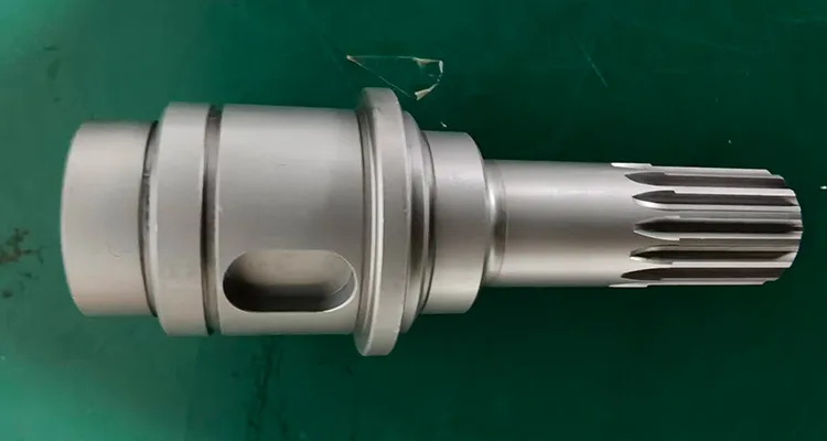
- Stepped Shafts: The most common configuration in power transmission systems. Stepped and hollow shaft manufacturing requires precise machining of transition shoulders to mitigate stress concentration and ensure exact bearing seating.
- Hollow Shafts: Designed to reduce weight or allow internal fluid/cable passage. Machining hollow shafts introduces structural wall thinness, which complicates workholding and increases the risk of radial deformation.
- Irregular Shafts: Includes splined shafts, camshafts, and crankshafts. These components require advanced multi-axis machining, profile grinding, or specialized index fixtures.
Rigid vs. Flexible Shafts: L/D Ratio Considerations
We classify shafts mechanically by their length-to-diameter ratio (L/d). This ratio dictates the tool path planning, spindle speed limits, and workholding configurations:
- Rigid Shafts (L/d≤12): These shafts exhibit high structural rigidity and resist bending under radial cutting forces. We machine them with standard workholding, such as a three-jaw chuck or between centers, without auxiliary support.
- Flexible/Slender Shafts (L/d>12): As the L/d ratio increases, the shaft becomes highly susceptible to tool deflection, vibrational chatter, and centrifugal whip.
Radial cutting forces will push a slender shaft right off center if you don’t support it. We add steady rests or follower rests at intermediate points to hold the part straight. Skip that support and you’ll see it immediately — taper that reads way out at the midpoint, a rough finish from chatter, and runout that fails inspection every time.
Shaft Tolerance Allocation & DFM Optimization
Applying identical tight tolerances to every journal on a shaft profile drives up custom shaft manufacturing costs unnecessarily. A strategic Design for Manufacturing (DFM) review differentiates critical mating surfaces from non-critical clearances. We work closely with our clients to establish a graded tolerance structure, applying high-precision limits only where functional requirements demand them.
Dimensional Tolerances: Bearing vs. Transmission Journals
We segment dimensional tolerances into two primary functional categories:
- Bearing Journals (Supporting Shaft Journals): These critical mounting surfaces interact directly with rolling element bearings. To ensure precise radial location and prevent rotational vibration, we hold these diameters to IT5 to IT7 tolerances.
- Transmission Journals: These segments mate with torque-transmitting components like gears, pulleys, or couplings. We advise clients to relax these tolerances to IT6 to IT9. This range accommodates robust interference or clearance fits without requiring the costly, ultra-tight limits of bearing seats.
The 4 Critical GD&T Categories for Shaft Machining
What actually matters for high-speed operation is the geometry — how round, how straight, how coaxial. We track four GD&T categories on every precision shaft:
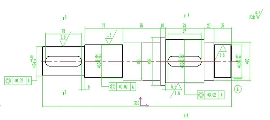
- Form: This controls roundness and cylindricity. While often governed by the limits of size, high-rpm applications demand independent cylindricity callouts to avoid localized high spots that disrupt bearing seating.
- Orientation: We control the perpendicularity of locating shoulders relative to the shaft axis, alongside the parallelism between critical axial faces. This ensures perpendicular thrust face alignment.
- Location: Controlling internal and external shaft coaxiality and runout tolerances prevents dynamic imbalance. For multi-stepped shafts, maintaining datum coincidence during machining is essential to align the axis of every step.
- Runout: We specify radial runout on key mating surfaces. Controlling radial runout ensures smooth torque transmission and prevents premature fatigue failure of adjacent bearings.
Surface Roughness Standards
Surface finish directly affects friction, wear resistance, and oil seal performance. We machine and inspect shafts to the following standards:
| Journal Type | Surface Roughness Range | Verification Method |
|---|---|---|
| Bearing Journals | Ra 0.2 to 1.6 μm | High-precision CNC cylindrical grinding followed by stylus roughness testing. Achieving a Ra 0.2 surface roughness limit minimizes frictional heat in high-speed spindles. |
| Transmission Journals | Ra 0.4 to 3.2 μm | Hard turning or fine grinding, verified with calibrated surface roughness testers. |
Shaft Workholding Methods: Maintaining Datum Coincidence
In precision shaft machining, maintaining geometric relationships across multiple steps requires strict datum coincidence. If the design, manufacturing, and inspection datums do not align, the resulting datum shift between setups will stack up critical geometric errors.
The Standard Approach: Two Center Holes
For solid stepped shafts, we locate the workpiece between dual 60-degree center holes to preserve alignment:
- Datum Coincidence Principle: Machining between centers aligns the workpiece’s rotational axis with the machine spindle’s center. This unified datum allows us to turn multiple diameters and shoulders in a single setup, minimizing cumulative runout.
- Rough Machining Adaptation: Because center holes lack the structural rigidity required for heavy roughing, we switch to a chucked setup or a “one clamp and one center” configuration to prevent workpiece slippage and vibration.
Workholding Strategies for Hollow & Thin-Walled Shafts
Once you drill or bore through the center, the original center holes are gone — and with them, your primary locating datum for finish turning. No solid datum means you’re re-chucking on a bore that might not be perfectly concentric, and runout goes through the roof.
We resolve this using three dedicated workholding methods:
- Internal Taper Method: For small bores (<2 mm), we chamfer the entry to a 60-degree internal taper to act as a temporary center hole.
- Taper Plug Method: For straight cylindrical bores, we press-fit custom 1:500 taper plugs into both ends to provide a solid locating center. If the bore itself is tapered, the plug’s taper must match the bore angle precisely.
- Mandrel with Taper Plug: For large taper through-holes, we mount the shaft onto a dedicated mandrel equipped with a matched taper plug to align the bore centerline with the spindle.
Note: Once we press-fit a 1:500 taper plug or mandrel, our machinists must not remove or adjust the fixture until all finish machining is complete. Removing the plug mid-process introduces re-clamping runout that ruins concentricity.
Struggling with hollow shaft runout? Contact our engineering team for a drawing and workholding evaluation.
Heat Treatment Sequencing: Preventing Distortion in Custom Shafts
We resolve this by applying a strict three-stage processing route: rough machining, semi-finish machining, and precision grinding.
Pre-machining: Normalizing & Annealing
Before any cutting tool touches raw material—particularly forgings or heavy bar stock—we perform normalizing or annealing. This initial thermal treatment serves three key purposes:
- Refining Grain Structure: Normalizing homogenizes the microstructural grain distribution across the workpiece cross-section.
- Eliminating Forging Stress: Slow, controlled cooling relieves the inherent casting or forging stresses that would otherwise cause the raw stock to warp during initial skin cuts.
- Improving Machinability: Annealing reduces material hardness to a consistent, machinable range, which improves tool life and chip control during heavy roughing.
Between Rough and Semi-Finish: Quenching & Tempering
After rough turning removes the bulk of the metal, we execute quenching and tempering (Q&T):
- Optimizing Mechanical Properties: This thermal cycle transforms the shaft’s core structure into tempered martensite or sorbite, providing high yield strength paired with excellent impact toughness.
- Why at This Stage? Roughing removes up to 70% of the material volume, which drastically alters the stress state of the workpiece. Performing quenching and tempering immediately after roughing allows the material to warp during the rapid quench phase when there is still ample machining stock (typically 1.5 to 3.0 mm on the diameter) to correct those runout errors during the subsequent semi-finish turning stage.
Before Finish Grinding: Surface Quenching & Aging
Prior to final grinding, the shaft must achieve high surface hardness on bearing or gear seat areas while maintaining a tough, ductile core.
- Localized Surface Hardening: We utilize induction or flame hardening to raise the wear resistance of critical journals to 50–60 HRC. While surface quenching inevitably introduces localized thermal distortion, our semi-finish machining leaves just enough grinding stock (usually 0.2 to 0.5 mm) to grind out the runout.
- Low-Temperature Aging: For ultra-high precision shafts, machining and local hardening leave micro-residual stresses that can cause the shaft to warp months after leaving our facility. To prevent this, we introduce a low-temperature aging cycle (typically 150°C to 200°C for 10 to 24 hours) after induction hardening or rough grinding. This process relieves residual stresses, guaranteeing the shaft remains straight and dimensionally stable even after long-distance maritime transport to overseas clients.
Material Selection for Shaft Manufacturing
Pick the wrong material or blank process and you’re fighting problems for the entire production run — fatigue cracks at the keyway, journals that wear out prematurely, shafts that move out of spec after a year in service. We walk clients through alloy and blank selection based on what the shaft actually sees: torque levels, operating speed, and the environment it runs in.
Common Shaft Alloy Steels & Application Cases
Standard shafts: AISI 1045 (45 steel) for cost-effective general applications.
Precision/Wear-Resistant: AISI 5140 (40Cr), AISI 52100 (GCr15), or 65Mn. GCr15 offers superior rolling-contact fatigue strength after quenching.
High-Speed/Heavy-Duty:
- Carburizing grades (e.g., 20CrMnTi, 20Cr, 20Mn2B): Provide a hard shell (58-62 HRC) with a tough, impact-absorbing core.
- Nitriding grade (38CrMoAl): Achieves high hardness via low-temp treatment (500-550°C) without quenching distortion.
Bar Stock vs. Forged Blanks: Selection Criteria
- Recommended for large, stepped, or highly stressed shafts. Forging:
- Aligns grain flow continuously along the shaft’s contours;
- Eliminates micro-porosity and refines the cast structure;Enhances tensile, bending, and torsional strength, significantly improving fatigue resistance at stress risers like keyways and shoulders.
Why Partner with Hansheng for Custom Shaft Manufacturing?
Hansheng delivers true precision by harmonizing material chemistry, machining, and thermal processing. We conduct comprehensive DFM reviews for every project—strictly controlling tolerance allocations and heat treatment sequences to prevent distortion. For hollow shafts, custom 1:500 taper plugs are used to maintain datum coincidence, eliminate runout, and maximize service life.
We back every shaft with full quality documentation:
- Material Certifications: Full heat traceability, chemical composition, and mechanical property reports.
- Surface Roughness Reports: Profilometer verification for critical journals, down to Ra 0.2.
- CMM Metrology Reports: Multi-axis CMM data confirming cylindricity, coaxiality, and runout tolerances.
FAQ
The most effective way is through smart tolerance zoning. Many engineers over-tolerance the entire shaft. We recommend applying high precision (IT5-IT7 and Ra 0.2-1.6μm) only to the bearing journals where assembly accuracy is critical. For transmission journals (mating with gears or pulleys), relaxing the tolerance to IT6-IT9 (Ra 0.4-3.2μm) can significantly reduce machining time and costs without affecting performance.
Long shafts (where the Length/diameter ratio is ≥ 12) are prone to thermal distortion. We prevent this by strictly separating rough and finish machining and inserting proper heat treatments. We perform normalizing before roughing to remove forging stress, apply quenching and tempering (Q&T) before semi-finishing, and for ultra-precise shafts, we add a low-temperature aging process after rough grinding.
Hollow shafts are challenging because drilling the center hole removes the standard center datums. To maintain the “datum coincidence principle,” our engineers use a custom 1:500 taper plug or a mandrel with a taper plug. Our rule in the shop is that once the taper plug is installed, it is never removed or replaced until all critical precision grinding surfaces are completely finished.
While 45 steel and 40Cr are great for standard applications, high-speed and heavy-load environments require superior fatigue strength and surface hardness. We highly recommend carburizing steels like 20CrMnTi or nitriding steels like 38CrMoAl.