Gear Shaft Machining Process: A Complete Manufacturing Case Study (45 Steel, DIN 6 Precision)
Blog 2026-07-23
This article walks through the complete gear shaft machining process for an actual production run of a 45 steel shaft with DIN 6 gear accuracy. The heat treatment route includes normalizing, quenching and tempering at 250–270 HBW, followed by localized high-frequency induction hardening on the tooth flanks to 48–52 HRC.
You get a complete process sequence, from raw bar stock to final inspection, with specific cutting parameters, stock allowances, and inspection methods.
Disclaimer: This is a real-world manufacturing case from Hansheng Automation. Certain proprietary features and exact dimensions have been modified for intellectual property protection.
Gear Shaft Drawing Analysis: Key Design Features and Precision Requirements
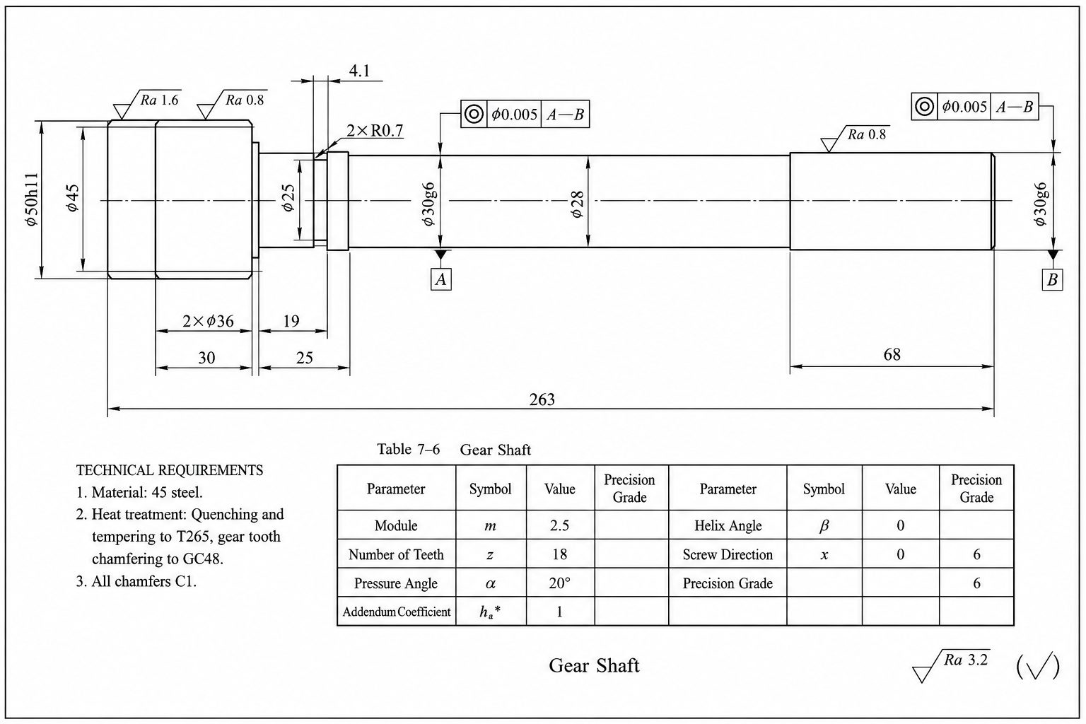
Datum and Dimensional Tolerances
The common axis of the two φ30g6 outer diameters serves as the primary datum. These journals locate the shaft in the final assembly bearings, so their coaxiality must be maintained throughout machining. The g6 tolerance band (approximately −7 μm to −20 μm for 30 mm nominal size) indicates a precision fit that requires grinding as the final operation, as turning alone cannot reliably achieve this band after heat treatment.
Gear Precision Grade: What ISO/DIN 6 Really Means
ISO/DIN 6 gear accuracy calls for profile and helix deviations typically within 6–9 μm, and pitch cumulative error within 20–30 μm for this part size. These limits are finer than what hobbing can deliver in production; grinding is therefore specified to finish the gear teeth after heat treatment.
Material and Heat Treatment Specifications
The drawing specifies 45 steel with two distinct hardness requirements: bulk quenching and tempering at 250–270 HBW for the entire shaft, and localized high-frequency induction hardening at 48–52 HRC applied only to the tooth flanks. The bulk treatment provides core strength and toughness for torque transmission, while the localized hardening adds wear resistance to the contact surfaces without introducing excessive distortion or brittleness in the journal areas.
Complete Gear Shaft Machining Process: 14-Step Manufacturing Workflow
The 14 operations break down into six distinct phases. Each phase addresses a specific manufacturing goal, with equipment and tooling selected accordingly.
1: Stock Preparation and Pre-Treatment
| Item | Detail |
| Equipment | Bandsaw, box furnace |
| Tooling | — |
The process begins by cutting the 45 steel round bar to φ55×380. We then normalize the blank at the box furnace to refine the as-rolled structure and improve machinability for the rough turning that follows.
2: Rough Turning
| Item | Detail |
| Equipment | Brother TC-S2A CNC Lathe |
| Tooling | Self-centering chuck, 45° chamfer tool, 90° external turning tool |
Rough turning is performed on both ends across two setups.The first setup machines the right-end diameters to φ38, leaving 2 mm for finishing. Flip the workpiece and rough-turn the left-end diameters, including the φ50h11 journal to φ53 and the extension section to φ32×107.
Machining tip:The 2 mm allowance must clear any scale and runout from the as-rolled bar, but not require excessive finishing passes. The two-setup approach introduces a potential concentricity error between the left and right sections—the self-centering chuck provides repeatable clamping, but the operator must check runout after each flip.
3: Quenching and Tempering
| Item | Detail |
| Equipment | Box furnace |
| Tooling | — |
The entire shaft is then heated to achieve a bulk tempering hardness of 250–270 HBW. This treatment is positioned between rough and finish turning because the workpiece will distort and develop surface scale during heating. The 2 mm roughing allowance accommodates this distortion and provides clean material for finishing.
4: Finish Turning and Center Hole Establishment
| Item | Detail |
| Equipment | Horizontal lathe |
| Tooling | Self-centering chuck, B2.5 center drill, 90° external turning tool, grooving tool, 45° chamfer tool |
Finish-turn the right end to the final dimensions except the two φ30g6 journals, which are left at 30.30. Drill and ream the first B2.5 center hole. Flip the part and repeat on the left end, leaving the same 0.30 mm stock on the extension section.
Crucial step:The center holes are drilled and reamed in this phase, not ground until after heat treatment. They serve as the locating reference for the grinding operations. Accuracy in center hole position and geometry during this step directly affects final runout.
5: Gear Hobbing
| Item | Detail |
| Equipment | Hobbing machine |
| Tooling | Pre-grinding gear hob |
The gear teeth are cut using a pre-grinding hob on the Ningjiang YK3610Ⅳ CNC Horizontal Gear Hobbing Machine. With its 200 mm maximum workpiece diameter capacity, this machine easily accommodates our φ55 shaft stock, ensuring highly stable cutting dynamics and leaving exactly 0.20 mm of stock evenly distributed on each tooth flank.
Why this matters:Stock uniformity matters more than the hobbing accuracy itself. Uneven allowance causes the grinding wheel to engage unevenly, resulting in inconsistent cycle times and potential burning on the tooth surfaces.
6: High-Frequency Induction Hardening
| Item | Detail |
| Equipment | High-frequency induction heating unit, tempering furnace |
| Tooling | Induction coil |
Induction heating is applied strictly to the tooth flanks to achieve 48–52 HRC at the surface, ensuring the core retains its tempered toughness. The high-frequency setup localizes heating to the gear tooth region within seconds.
Process control:Heat input must be precisely controlled. Insufficient case depth leads to premature contact fatigue; excessive heating can penetrate to the tooth root, altering the core hardness distribution established during tempering. The tempering cycle immediately after induction hardening relieves residual stress and minimizes cracking risk during grinding.
7: Precision Grinding – Center Holes, Journals, and Gear Teeth
| Item | Detail |
| Equipment | Center hole grinder, external grinder, gear grinder |
| Tooling | Grinding wheels (various specifications), dressing tools |
The final stage starts by grinding the two B2.5 center holes to re-establish the common axis. The workpiece is then moved to the external grinder to finish the φ30g6 journals to the g6 tolerance, achieving Ra 0.8 μm. Finally, the gear grinder is set up to remove the remaining 0.20 mm stock to reach Grade 6 accuracy, Ra 1.6 μm tooth surface finish.
The sequence is fixed—center holes establish the reference, journals are ground next to confirm runout between the two bearing seats, and gear grinding is last because it references off the ground journals for axial positioning. Grinding the extension section to φ30 at this stage is purely functional; it will be cut off in the final operation.
The Heat Treatment Strategy: Normalizing, Tempering, and Induction Hardening
The drawing calls for three separate heat treatment operations, each positioned at a specific point in the process sequence.
Normalizing
Normalizing is applied to the as-cut bar stock before any machining. The 45 steel round bar arrives with a rolled microstructure that varies from the surface to the center. Normalizing heats the entire blank above the transformation temperature and air-cools it, producing a refined, uniform pearlite-ferrite structure throughout the cross-section.
The immediate benefit is improved machinability. A normalized structure produces consistent chip formation and predictable tool wear during rough turning. Without this step, the as-rolled bar may exhibit hard spots or grain non-uniformity that accelerates insert edge breakdown.
Quenching and Tempering
Positioned after rough turning, quenching and tempering treats the entire shaft to 250–270 HBW. The process develops a tempered sorbite structure—fine spheroidal carbides dispersed in a ferrite matrix—which provides the best combination of strength and toughness for this medium-carbon steel. This hardness range corresponds to a tensile strength of approximately 800–900 MPa, suitable for transmission shafts under torsion and bending loads.
Placing this treatment after rough turning is intentional. The thermal cycle causes distortion and surface decarburization; the 2 mm allowance left on all diameters provides material to clean up these effects during finish turning.
High-Frequency Induction Hardening and Tempering
This operation applies localized hardening to the gear tooth flanks only, raising surface hardness to 48–52 HRC while the tooth core remains at the tempered hardness level.
The induction coil heats the tooth surface above the austenitizing temperature within seconds, followed by immediate quenching. The rapid heating and cooling cycle limits heat penetration to the case depth—typically 1–2 mm below the tooth root—preserving the core toughness established during tempering.
The low-temperature tempering immediately after induction hardening reduces residual stress from the rapid quench and stabilizes the hardened structure.
Why Not Harden Everything During Tempering?
Quenching and tempering cannot simply be extended to a higher hardness. If the entire shaft were hardened to 48 HRC, the bearing journals would lose toughness and become susceptible to fracture under impact loads. The gear teeth, however, require high surface hardness for contact fatigue resistance. The solution is a two-stage approach: bulk tempering for core properties, followed by localized case hardening for wear resistance.
Sequence Logic
The three treatments are ordered to minimize interactions between thermal distortion and machining accuracy:
Normalize → rough turn → quench and temper → finish turn → hob → induction harden → grind
Normalizing happens before any cut. Quenching and tempering occurs after rough turning, so distortion and scale are removed during finish turning. Induction hardening follows hobbing, allowing gear grinding to remove the final 0.20 mm and correct any heat-induced runout. This sequence ensures each operation works on a clean, consistent workpiece.
How We Achieve DIN 6 Gear Accuracy on Stepped Shafts
Holding DIN 6 gear accuracy on a shaft with multiple stepped diameters requires a disciplined approach to datum management. The following three practices are what separate a successful run from a scrap bin.
Center Hole as the Machining Datum
The B2.5 center holes drilled at finish turning establish the reference axis for all subsequent grinding operations. These center holes are reamed immediately after drilling to ensure the 60° center angle and surface finish are correct for subsequent locating. Any error at this stage multiplies through the grinding sequence.
At center hole grinding, the center holes are ground again, not just re-drilled. Heat treatment distorts the original center holes; grinding them removes this distortion and re-establishes the common axis on a clean, undamaged surface. Two center holes from both ends, ground on the same machine in a single setup, produce an axis that passes through both bearing journal centers.
Concentricity Control Between Stepped Diameters
The two φ30g6 journals share a common axis by drawing requirement. This is achieved through a combination of finish turning and grinding. During finish turning, both journals are turned to 30.30 in two separate setups—one per end. The self-centering chuck provides repeatable clamping, but the work is flipped between operations, so the concentricity at this stage depends entirely on chuck repeatability.
The cylindrical grinding phase corrects whatever concentricity error was introduced during finish turning. The workpiece is mounted between the two ground center holes, not in a chuck. This centers the part on its own axis, independent of any previous clamping errors. Both φ30g6 journals are ground in one continuous setup, removing the 0.30 mm stock from both surfaces without re-clamping between them. This is how the common-axis requirement is actually met.
Stock Allowance for Grinding
The 0.30 mm stock left on the φ30g6 journals at finish turning serves two opposing purposes. It must be large enough to cover three sources of error: runout from the finish turning operation, scale and decarburization from quenching and tempering, and thermal distortion from induction hardening. The hobbing step and the subsequent induction hardening of the gear teeth do not affect these journals directly, but the shaft as a whole distorts slightly during both thermal cycles.
At the same time, 0.30 mm cannot be excessive. External grinding is a slow operation. Removing 0.30 mm from each journal is typically achieved in two passes—a rough grinding pass followed by a finishing pass. A 0.50 mm allowance would require three passes and extend cycle time without improving accuracy. The 0.30 mm figure represents the balance between safely covering distortion and minimizing grinding cost.
Grinding Sequence: Journals Before Gear Teeth
Gear grinding locates the workpiece off the finished journals—specifically, the two φ30g6 bearing seats. This means the journals must be finished before the gear teeth can be ground. The sequence is fixed: grinding the gear teeth first would leave no clean, accurately ground surface on the shaft to clamp or center the part for journal grinding.
At cylindrical grinding, the external grinder finishes both φ30g6 journals to the g6 tolerance and Ra 0.8 μm. The gear grinder then uses these finished journals as locating references, either by direct clamping or by referencing their surfaces for axial position. This ensures the gear tooth profile runs true to the bearing axis. If the journals were ground after the teeth, any runout in the grinding process would shift the bearing axis relative to the tooth profile, violating the datum requirement on the drawing.
Conclusion – Why This Case Study Matters for Your Gear Shaft Sourcing
Sourcing a gear shaft is not about finding a shop that owns a gear grinder. It is about finding one that sequences operations correctly.
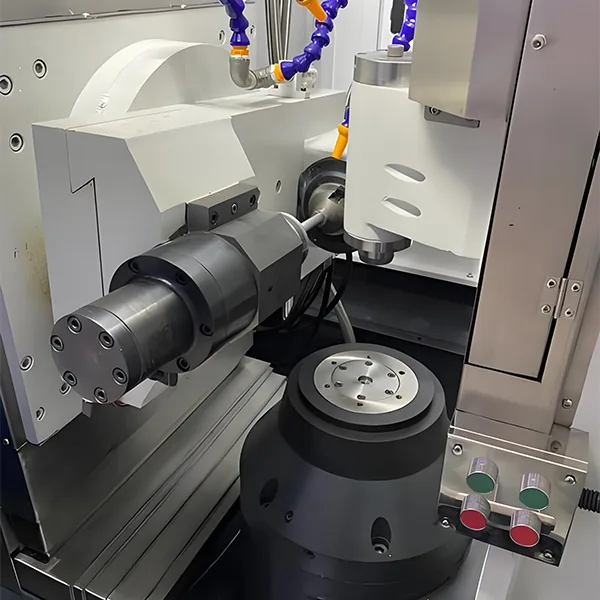
This case highlights a point often overlooked in sourcing decisions: flexible production capability. For small-to-medium batch jobs, achieving DIN 6 precision doesn’t require a rigid, specialized production line. By pairing high-precision CNC equipment with expertly sequenced setups, the process remains highly repeatable across a wide range of shaft geometries without passing significant retooling costs onto the customer.
When evaluating a manufacturing partner for your next gear shaft project, ask them two critical questions:
- How do you manage the datum transition from turning to grinding?
- Do you re-grind the center holes after heat treatment?
The answers will reveal more about their true machining capability than a simple equipment list.Ready to optimize your custom gear shaft manufacturing? Contact our engineering team today with your drawings and specifications for a comprehensive process review and quote.
FAQ
Concentricity is strictly maintained by grinding both bearing journals in a single, continuous setup between ground center holes. This avoids any re-clamping errors between passes. Crucially, the center holes themselves are re-ground after heat treatment to correct thermal distortion and establish a flawless common axis.
Leaving a calculated stock allowance, such as 0.30 mm, balances precision and cost. It is large enough to clean up surface scale, decarburization, and distortion caused by quenching and induction hardening. Simultaneously, it prevents excessive grinding cycles, typically requiring only one roughing and one finishing pass to achieve the final tolerance.
Distortion is heavily mitigated through three specific process controls:Precise induction coil design to strictly localize heat on the tooth flanks. Controlled cycle times to prevent excessive heat penetration into the core. Immediate low-temperature tempering following the quench to relieve residual stress and stabilize the microstructure.
DIN 6 (ISO 1328 Grade 6) limits tooth profile and helix deviations to approximately 6–9 μm, and pitch cumulative error to 20–30 μm for moderate-sized gears. Because hobbing cannot reliably hit these micro-tolerances, we achieve DIN 6 accuracy through a final CNC gear grinding operation that uses the finished bearing journals as the locating datum.
We provide comprehensive quality documentation for every batch. The standard reporting package includes:
Dimensional Data
Geometric Tolerances
Surface Finish
Gear Parameters