Worm wheel vs gear: key differences
Blog 2026-09-07
Worm wheels and conventional gears both transmit rotary motion and torque, but they work in different ways. The main differences are the mating components, tooth geometry, contact conditions, and transmission characteristics.
A conventional gear typically meshes with another gear or a rack. A worm wheel is designed to mesh with a worm, forming a worm gear drive. These differences affect efficiency, reduction ratio, heat generation, and the conditions in which each transmission type is used.
Mating components
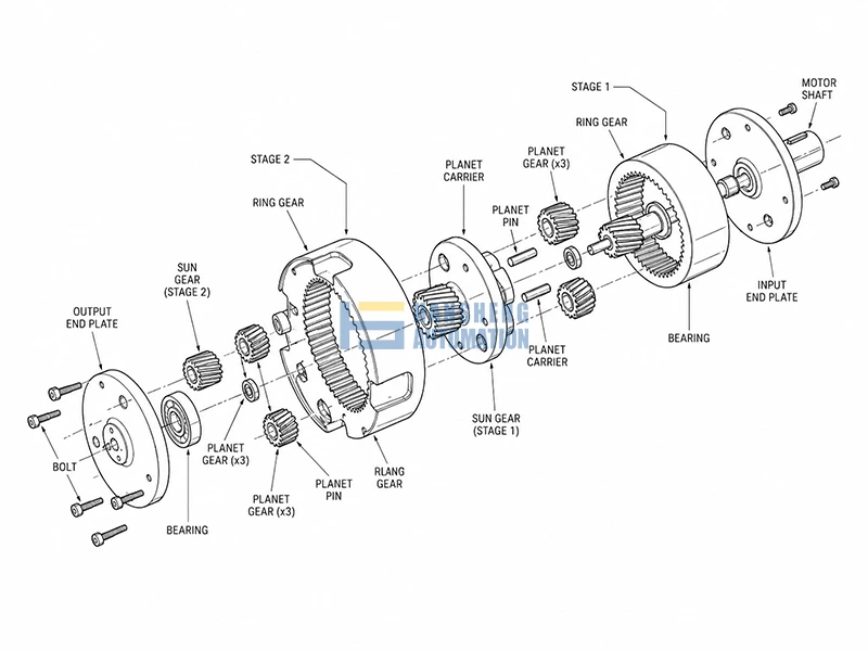
A conventional gear typically meshes with another gear to form a gear drive. Gears can also mesh with a rack when rotary motion needs to be converted into linear motion.
A worm wheel works with a worm. The worm has a screw-like helical tooth form, while the worm wheel has a tooth surface designed to mesh with it.
The two components are therefore designed as a matched pair. Their geometry and operating conditions determine how the worm gear drive transmits motion and torque.
Tooth geometry
Conventional gears use different geometries depending on the transmission requirements. Common examples include spur, helical, and bevel gears.
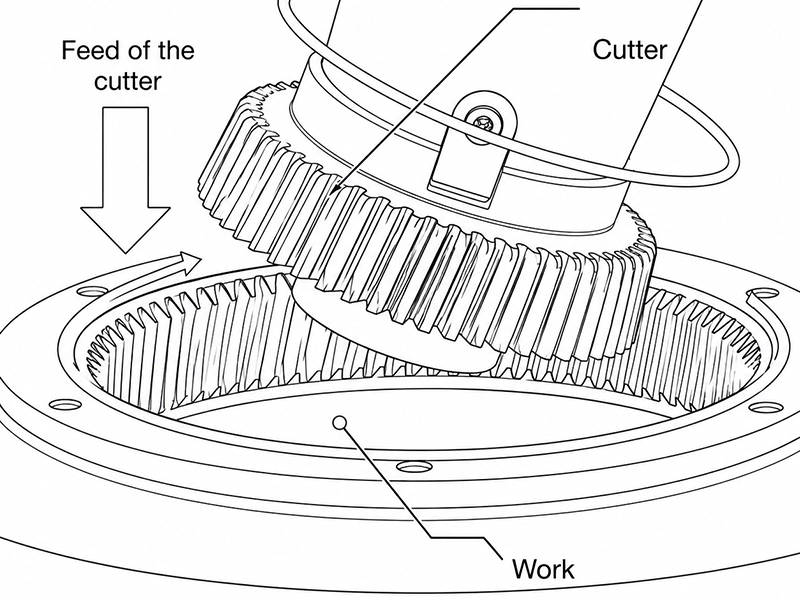
A worm wheel has a helical-like tooth arrangement, but its tooth surface is specifically generated to mesh with the worm. Depending on the worm gear geometry and manufacturing method, the wheel may have a concave tooth surface that provides a larger contact area with the worm.
The geometry of a worm wheel can vary with the worm profile, center distance, material, and manufacturing process. Plastic and powder-metallurgy worm wheels, for example, may be produced using molding, pressing, or other near-net-shape processes rather than the same machining process used for metallic worm wheels.
For this reason, a worm wheel should not be treated simply as a conventional helical gear. Its tooth geometry is part of the worm-and-wheel transmission design.
Transmission efficiency
Conventional gear drives generally have higher transmission efficiency than worm gear drives.
The main difference comes from the contact between the mating surfaces. Conventional gear pairs have a combination of rolling and sliding contact. Worm gear drives involve a greater amount of sliding contact between the worm and wheel.
This sliding produces friction and power loss, which can also result in more heat during operation.
Conventional gears are therefore commonly used when transmission efficiency, speed, or power capacity is a major consideration. Worm gear drives trade some efficiency for other advantages, such as a high reduction ratio and compact arrangement.
Reduction ratio
A worm gear drive can provide a high reduction ratio in a single stage.
Conventional gear systems can also achieve high overall reduction ratios, but multiple gear stages may be required. A worm gear drive can achieve a large speed reduction without using the same number of stages.
This makes worm gear drives useful when a high reduction ratio is needed within a relatively compact transmission arrangement.
Self-locking
Worm gear drives can provide self-locking behavior under certain conditions.
Self-locking depends on factors such as the worm lead angle, friction, lubrication, materials, and operating conditions. A worm gear drive should therefore not be assumed to be self-locking simply because it uses a worm and worm wheel.
When resistance to back-driving is required, the actual worm gear design and operating conditions need to be considered.
Heat and wear
The higher sliding contact in a worm gear drive can increase friction and heat generation compared with many conventional gear arrangements.
Lubrication, heat dissipation, material selection, and operating speed are therefore important considerations for worm gear drives. Wear also needs to be considered, particularly when the transmission operates under high loads or for long periods.
Conventional gears can also generate heat and experience wear, but their lower sliding losses generally allow higher efficiency under suitable operating conditions.
Worm wheel vs gear: quick comparison
| Feature | Conventional gear drive | Worm gear drive |
|---|---|---|
| Mating components | Gear + gear or gear + rack | Worm + worm wheel |
| Tooth geometry | Spur, helical, bevel, and other designs | Geometry designed to mesh with a worm |
| Reduction ratio | Moderate per stage | High per stage |
| Transmission efficiency | Generally higher | Generally lower |
| Sliding contact | Lower | Higher |
| Heat generation | Generally lower | Generally higher |
| Self-locking | Generally not available | Possible under certain conditions |
| Typical applications | High-speed and high-power transmission | High reduction and compact transmission |
Which one should you choose?
The choice depends on the requirements of the transmission.
A conventional gear drive is generally suitable when high efficiency, high speed, or high power transmission is important. Spur and helical gears are commonly used for different shaft arrangements and operating conditions, while bevel gears are used when the shafts intersect.
A worm gear drive is a practical option when a high reduction ratio or compact transmission arrangement is required. It may also be suitable when resistance to back-driving is needed and the operating conditions allow self-locking behavior.
The selection should also consider load, input speed, duty cycle, lubrication, heat dissipation, allowable backlash, service life, and available installation space.
Conclusion
Worm wheels and conventional gears differ in their mating components, tooth geometry, contact conditions, and transmission characteristics.
Conventional gear drives generally provide higher efficiency and are suitable for many high-speed and high-power applications. Worm gear drives can provide a high reduction ratio in a compact arrangement and may offer self-locking behavior under suitable conditions.
The right choice depends on the required speed, torque, reduction ratio, efficiency, space, and operating conditions.