How Torque Flows Through a 2-Stage Planetary Gearbox: Sun Gear to Planet Carrier in Humanoid Robot Actuators
Blog 2026-06-18
The planetary gearbox actuator is what makes humanoid robot joints possible. A typical BLDC motor used in a humanoid robot joint weighs under 300 grams and outputs somewhere between 3-8 Nm of peak torque at its shaft — yet the knee joint of an 80 kg humanoid robot must absorb peak impact loads exceeding 150 Nm during walking, sustained repeatedly, thousands of cycles per day.A typical BLDC motor used in a humanoid robot joint weighs under 300 grams and outputs somewhere between 3-8 Nm of peak torque at its shaft. Yet the knee joint of an 80 kg humanoid robot must absorb peak impact loads exceeding 150 Nm during walking — and sustain that repeatedly, thousands of cycles per day.
A more powerful motor alone cannot close the gap. It is closed by a two-stage planetary gearbox sitting between the motor and the joint output. Understanding exactly how torque travels from the sun gear through to the planet carrier — and why two stages are stacked rather than one — is the engineering question this article works through, step by step.
Actuator designers, procurement engineers, and system integrators working on humanoid robot joints all face the same upstream decision: how the gearbox is specified determines whether the joint meets its torque, backdrivability, and envelope requirements simultaneously.
At Hansheng Automation, we manufacture precision gears and gear components used in planetary actuators for humanoid robotics — including the internal ring gears, sun gears, and planet gears.
Why Humanoid Robots Require High-Torque-Density Planetary Gearboxes
A full-size humanoid robot typically integrates between 25 and 30 rotary actuators across its joints. The torque requirements vary significantly by location: wrist and finger joints may operate below 10 Nm, while hip and knee joints routinely face peak loads in the 60–250 Nm range during dynamic tasks such as stair climbing, load carrying, or recovery from stumble.
Meeting those loads in a joint-mounted package — where diameter, axial length, and mass are all constrained — rules out most conventional transmission architectures. Three options dominate current humanoid actuator design, each with a distinct set of trade-offs.
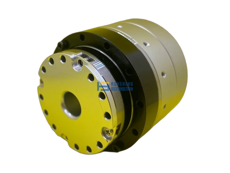
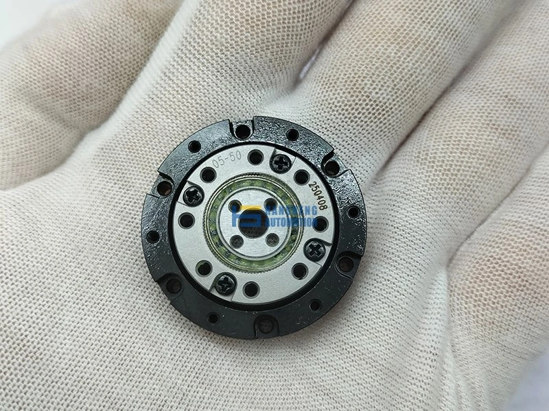
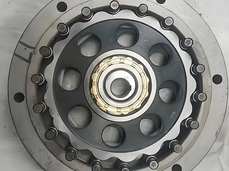
| Feature | Planetary Gearbox | Harmonic Drive | Cycloidal Reducer |
|---|---|---|---|
| Reduction ratio range | 3:1 – 100:1 (2-stage) | 30:1 – 320:1 | 30:1 – 300:1 |
| Backdrivability | Good (ratio-dependent) | Poor | Moderate |
| Torque density | High | Very high | High |
| Backlash | Low–moderate | Near-zero | Low |
| Manufacturing cost | Moderate | High | High |
| Shock load resistance | High | Low (flexspline fatigue) | High |
For joints that require backdrivability — the ability to be back-driven by external forces, which is critical for compliant control and fall recovery — harmonic drives are structurally disadvantaged. Their high reduction ratios create large reflected inertia and friction, making force transparency difficult without an output-side torque sensor.
Cycloidal reducers improve on shock resistance but introduce complexity in manufacturing and assembly that pushes unit cost up.
The two-stage planetary gearbox occupies a practical middle ground: compact robot actuator geometry, configurable reduction ratio, genuine backdrivability at ratios below roughly 50:1, and a cost structure that scales with production volume.
Single-Stage Planetary Gearbox: Components, Ratio Formula, and Torque Path
Before tracing torque through two stages, it helps to be precise about what one stage actually consists of and how load moves through it.
A single planetary stage has four functional members:
- Sun gear — the central input gear, driven by the motor shaft at high speed and low torque
- Planet gears — typically 3 to 4 gears that mesh simultaneously with both the sun gear and the ring gear, rotating on pins mounted to the carrier
- Ring gear — an internal-tooth gear that surrounds the planets; in standard reduction configuration, it is held fixed to the housing
- Planet carrier — the structural cage that holds the planet pins; as the planets orbit the sun, the carrier rotates and serves as the output
The reduction ratio for this fixed-ring configuration is:
i = 1 + (Z_ring / Z_sun)
Where Z_ring and Z_sun are the tooth counts of the ring and sun gears respectively. A typical example: Z_sun = 18, Z_ring = 54 gives i = 1 + 54/18 = 4:1.
Single-stage ratios practically range from 3:1 to 10:1. Beyond 10:1 in a single stage, the sun gear becomes too small relative to the ring gear to carry the load reliably.
Because three or four planet gears mesh simultaneously and share the load in parallel, each tooth contact carries only a fraction of the total torque. This distributed load path allows a planetary stage to achieve torque density two to three times higher than a comparable parallel-shaft gear pair of the same envelope — which is precisely why it fits inside a compact robot actuator joint.
Torque Path: Stage 1 — Sun Gear to Planet Carrier

Motor Shaft → Sun Gear
The motor delivers rotation to the sun gear directly — high angular velocity, relatively low torque. The sun gear is the smallest gear in the stage, which is why input speed is high: it completes multiple revolutions for every single revolution of the output.
Sun Gear → Planet Gears (Spin + Orbit)
Each planet gear meshes with the sun gear and rotates on its own pin axis (spin), while simultaneously being constrained by the fixed ring gear to orbit around the sun gear — walking the circumference of the ring gear as it spins.
Ring Gear — The Fixed Reaction Member
The ring gear is not passive. It is the reaction member — it absorbs the tangential force that the planet gears push against it and converts that into the constraint that forces orbital motion. Without a fixed ring gear, the planets would simply push the ring gear into rotation and no useful output would occur.
The ring gear provides the ground reaction that enables the carrier to rotate. While each individual tooth only meshes with one planet at a time, the ring gear body as a whole must withstand the full, combined reaction torque of the entire stage and transmit it to the actuator housing. This is why the ring gear’s structural rigidity, material selection, and precise integration with the housing are critical to preventing elastic deformation under peak joint loads.
Case
In one recent project supplying internal ring gears to a Canadian humanoid robotics manufacturer, the platform’s compact actuator geometry left no tolerance for dimensional drift under load — ring gear components were specified to ISO/DIN Grade 6, with housing fit dimensions held to within a few microns to prevent elastic deformation at peak joint torque.
Accelerated development timelines on the platform meant production lead times were compressed significantly compared to standard industrial gear supply schedules, which required us to maintain tight coordination between machining, inspection, and delivery at each batch. That project reinforced something we see consistently in humanoid actuator supply: gear precision requirements in this segment are closer to aerospace tolerances than conventional industrial robotics, and delivery schedules reflect the pace of platform development rather than standard procurement cycles.
The Willis equation describes the kinematic relationship between all three members:
(ω_sun − ω_carrier) / (ω_ring − ω_carrier) = − Z_ring / Z_sun
When the ring is fixed (ω_ring = 0), this simplifies to:
ω_carrier = ω_sun × Z_sun / (Z_sun + Z_ring)
In plain terms: the carrier rotates in the same direction as the sun gear, but at a fraction of its speed — with torque increased by the inverse of that fraction, minus friction losses.
Planet Carrier → Stage 1 Output
The carrier collects the orbital motion of all planet gears simultaneously and converts it into a single, unified rotation at reduced speed and amplified torque. With the Z_sun = 18, Z_ring = 54 example from the previous section, the carrier rotates at 1/4 the speed of the sun gear, and torque at the carrier is approximately 4× the motor input torque (less mechanical losses, typically 2–5% per stage depending on lubrication condition, input speed, and gear surface finish quality).
Stage 2: Torque Multiplication from First-Stage Carrier to Final Output
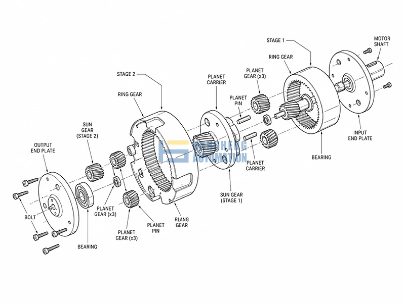
Stage 1 delivers a reduced-speed, amplified-torque rotation at its planet carrier. That is not the end of the transmission — it is the beginning of Stage 2.
The Carrier-to-Sun Interface: The Black Box Opened
The Stage 1 planet carrier is rigidly coupled to the Stage 2 sun gear — via a shared shaft, splined connection, or in compact actuator designs, machined as a single integrated component.
This means the output of Stage 1 becomes the input of Stage 2 with no intermediate gearing. Whatever speed and torque the Stage 1 carrier delivers, the Stage 2 sun gear receives exactly that — and the second planetary stage processes it through the same sun → planet orbit → fixed ring → carrier output path described in the previous section.
The Stage 2 ring gear is again fixed to the housing. The Stage 2 planet carrier becomes the final output of the entire gearbox — the shaft that connects to the robot joint.
This series arrangement is what makes the two-stage architecture powerful: each stage multiplies the ratio independently, and the total effect is their product.
Total Reduction Ratio
i_total = i₁ × i₂
If both stages are designed with Z_sun = 15 and Z_ring = 75:
i per stage = 1 + (75 / 15) = 6:1
i_total = 6 × 6 = 36:1
This is a ratio that a single planetary stage cannot reach without compromising sun gear size and load capacity. Two moderate stages in series achieve it cleanly, with both stages operating at geometry that supports adequate tooth strength and contact ratio.
Stage 1 and Stage 2 ratios need not match. In practice, actuator designers sometimes use a slightly higher ratio in Stage 1 (where speeds are highest and torques lowest) and a lower ratio in Stage 2 (where loads are heavier), to balance bearing life and gear tooth stress across the assembly.
Output Torque Calculation
Total efficiency for a two-stage planetary gearbox is the product of per-stage efficiencies. A well-manufactured planetary stage typically runs at 95–98% mechanical efficiency under adequate lubrication and normal operating temperatures; two stages in series therefore deliver:
η_total = 0.97 × 0.97 ≈ 0.94(assuming 97% per stage; actual values vary with lubrication condition, operating speed, and gear surface finish)
The output torque formula is:
T_out = T_in × i_total × η_total
Applying this to a realistic humanoid knee joint actuator: a BLDC motor outputting 5 Nm at its shaft, driving a 36:1 two-stage planetary gearbox:
T_out = 5 × 36 × 0.94 ≈ 169 Nm
That figure sits comfortably within the 60–250 Nm range identified earlier as the operational requirement for hip and knee joints in load-bearing humanoid applications — delivered in an actuator package whose gearbox outer diameter typically falls between 60 and 100 mm depending on module and planet count selection.
The 6% efficiency loss (roughly 10 Nm in this example) manifests as heat at the gear mesh interfaces. In continuous-duty humanoid joints subject to frequent load reversals, this thermal load is a real design constraint — which is one reason actuator-level thermal management and gear surface finish quality both matter to sustained output torque, not just peak figures.
Note: The above data represents a typical application study. Because joint requirements vary significantly by robot weight and dynamic targets, we recommend contacting Hansheng Automation’s engineering team for customized gear calculations and component specifications tailored to your project.
Design Trade-offs: Backdrivability vs Reduction Ratio
Increasing the reduction ratio amplifies output torque — but it introduces a constraint that becomes critical in humanoid robotics: as the ratio rises, the gearbox becomes progressively harder to back-drive.
What Backdrivability Actually Means

A gearbox is backdrivable when an external force applied at the output shaft can cause the input shaft to rotate. During a fall, a non-backdrivable joint cannot absorb impact compliantly; the structure takes the load rigidly, which risks both hardware damage and injury in human-robot contact scenarios. In force-controlled walking, the controller needs to sense and respond to ground reaction forces through the joint — something that requires the transmission to transmit force bidirectionally with low resistance.
Where the Ratio Becomes a Problem
The relationship between reduction ratio and backdrivability is not linear, but a practical boundary exists. At ratios below approximately 30:1, a well-designed planetary gearbox with adequate lubrication and surface finish can generally be back-driven —though actual backdrivability depends on friction coefficient, bearing preload, and lubrication state specific to each design. Between 30:1 and 50:1, backdrivability typically degrades to the point where an output-side torque sensor is recommended to maintain force transparency — though specific behavior varies by design. Above 50:1, reflected inertia and friction at the output typically make compliant back-driving impractical for most humanoid joint applications — though this threshold can shift depending on motor inertia, gear geometry, and lubrication.
This creates a direct tension in actuator design: the knee joint needs 150+ Nm of output torque, which pushes toward high ratios — but compliant contact control pushes back toward lower ratios. There is no ratio that satisfies both requirements simultaneously without architectural compromise.
The QDD Response
The Quasi-Direct Drive (QDD) actuator architecture addresses this tension by accepting a different trade-off. Rather than using a high-ratio gearbox to compensate for a modest motor, QDD designs pair a high-torque-density motor with a low-ratio single or two-stage planetary gearbox — typically in the 6:1 to 12:1 range. The lower ratio preserves backdrivability and keeps reflected inertia low, while the motor itself contributes the bulk of the torque capacity.
The practical consequence is a larger, heavier motor for a given joint torque target — but a transmission that remains transparent to force control without requiring a dedicated torque sensor at every joint.
QDD architecture has become an increasingly common approach in research-grade humanoid and quadruped platforms where contact-rich locomotion and force control bandwidth are prioritized, though transmission selection ultimately depends on platform-specific torque and control requirements.
Real-Application: 2-Stage Gearbox Selection for Hip, Knee, and Ankle Joints
Not every joint in a humanoid robot carries the same transmission requirement. The selection logic follows torque demand fairly directly.
Hip, knee, and ankle joints in current full-size humanoid platforms typically operate in the 60–250 Nm range during dynamic tasks — figures that vary significantly by robot mass, gait profile, and task type. The specification envelope that Schaeffler’s two-stage planetary actuator (introduced at CES 2026) is explicitly designed to cover. The MyActuator RMD X6-40, used in several research humanoid platforms including AGILOped, applies the same two-stage architecture for the same reason: high torque output within a compact modular envelope.
Elbow and wrist joints typically fall below 40 Nm. Single-stage planetary or QDD architectures are usually sufficient here. Finger joints, where backlash and axial profile matter more than peak torque, more commonly use harmonic drives.
The dividing line in practice sits around 40–50 Nm output: below that threshold, two-stage complexity is rarely justified. Above it, stacking two moderate-ratio stages becomes the more practical path to meeting torque targets within joint envelope constraints.
FAQ
In a single stage, torque flows from sun gear to planets to carrier in one step. In a two-stage design, the first-stage carrier drives the second-stage sun gear, repeating the process. Total output torque is the product of both stages minus efficiency losses—5 Nm in becomes 150 Nm at the joint.
T_out = T_in × i_total × η_total, where i_total = (1 + Z_ring1/Z_sun1) × (1 + Z_ring2/Z_sun2). Example: 5 Nm input, 36:1 ratio, 94% efficiency → ≈169 Nm output. Loss dissipates as heat at gear mesh interfaces.
Below 30:1: generally backdrivable. 30–50:1: backdrivability degrades; output-side torque sensing recommended. Above 50:1: compliant backdriving is typically impractical for humanoid joints. QDD uses lower ratios (6–12:1) with larger motors to preserve backdrivability.
The dividing line is ~40–50 Nm output torque. Hip, knee, and ankle joints (60–250 Nm) require two stages. Elbow and wrist (<40 Nm) can use single-stage or QDD. Finger joints typically use harmonic drives where backlash and axial profile matter more than peak torque.