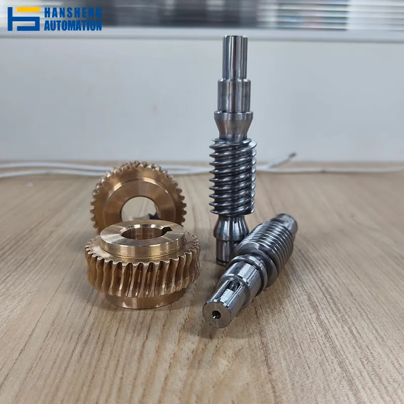
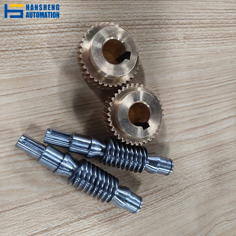
Worm and Wheel
Brand: Hansheng
Service Type: Custom Machining (OEM/ODM to Drawings)
Accuracy Grade: ISO/DIN/GB Level 5 (with grinding)
Gear Module: 0.1–7.0
Tip Diameter: 3 mm–500 mm
Drawings Accepted: PDF, STEP, DWG, IGES
Introduction
Drawing on more than ten years of experience in custom precision gear production, we manufacture custom worm and wheel sets tailored to your specific mechanical requirements and technical drawings.
From selecting the optimal material combinations (such as wear-resistant bronze alloys for worm wheels and hardened steel for worm shafts) to ensuring precise tooth profile alignment, we focus on delivering parts that integrate reliably into your mechanical assemblies.
Backed by our comprehensive in-house capabilities, which include CNC gear skiving, precision hobbing, shaping, and finish grinding, we are capable of achieving gear tolerances up to ISO/DIN Grade 5. Whether you require a single prototype for testing or a medium-to-large production batch, we are committed to providing practical, high-precision manufacturing solutions that align with your technical specifications.
Worm and Wheel Machining Capabilities & Specifications
To meet the stringent tolerance and performance requirements of custom worm and wheel systems, we utilize a range of advanced multi-axis CNC machines and dedicated gear-cutting equipment to deliver precise, made-to-order components.
Below is a summary of our primary manufacturing boundaries and the technical specifications we can achieve based on your drawings:
| Parameter | Standard Capability | Notes |
|---|---|---|
| Module Range | 0.1–7.0 | Standard and custom tooth profiles available |
| Outside Diameter (Tip Diameter) | 3–500 mm | Suitable for miniature to medium-sized worm gear assemblies |
| Gear Accuracy | Up to ISO 1328 Grade 5 | Achieved through precision finishing processes |
| Worm Wheel Hobbing (YK3610) | Maximum Module 3.0 Maximum Diameter 200 mm |
Preferred for external worm wheel manufacturing |
| Gear Shaping (YS5120CNC) | Maximum Module 4.0 Maximum Diameter 200 mm |
Suitable for internal gears and space-constrained profiles |
| Common Worm Materials | AISI 1045 (45 Steel), 40Cr, 20CrMnTi, Stainless Steel | Optional carburizing, Q&T, induction hardening, and nitriding |
| Common Worm Wheel Materials | Tin Bronze, Aluminum Bronze, Brass, Cast Iron, POM (Acetal), Nylon (PA6/PA66) | Selected for excellent wear resistance and low friction |
Actual production case:Custom ZCuSn10Zn2 Bronze Worm Wheel Manufacturing
To demonstrate how our engineering team translates technical drawings into high-performance components while strictly protecting our clients’ intellectual property (IP), the case study below utilizes an internal engineering reference drawing. This drawing represents a typical custom worm wheel project designed for industrial speed reducer applications.
*Please note: At Hansheng Automation, we sign strict Non-Disclosure Agreements (NDAs) with our clients and never publish proprietary designs. The drawing used below is an internal reference design used solely for technical demonstration.*
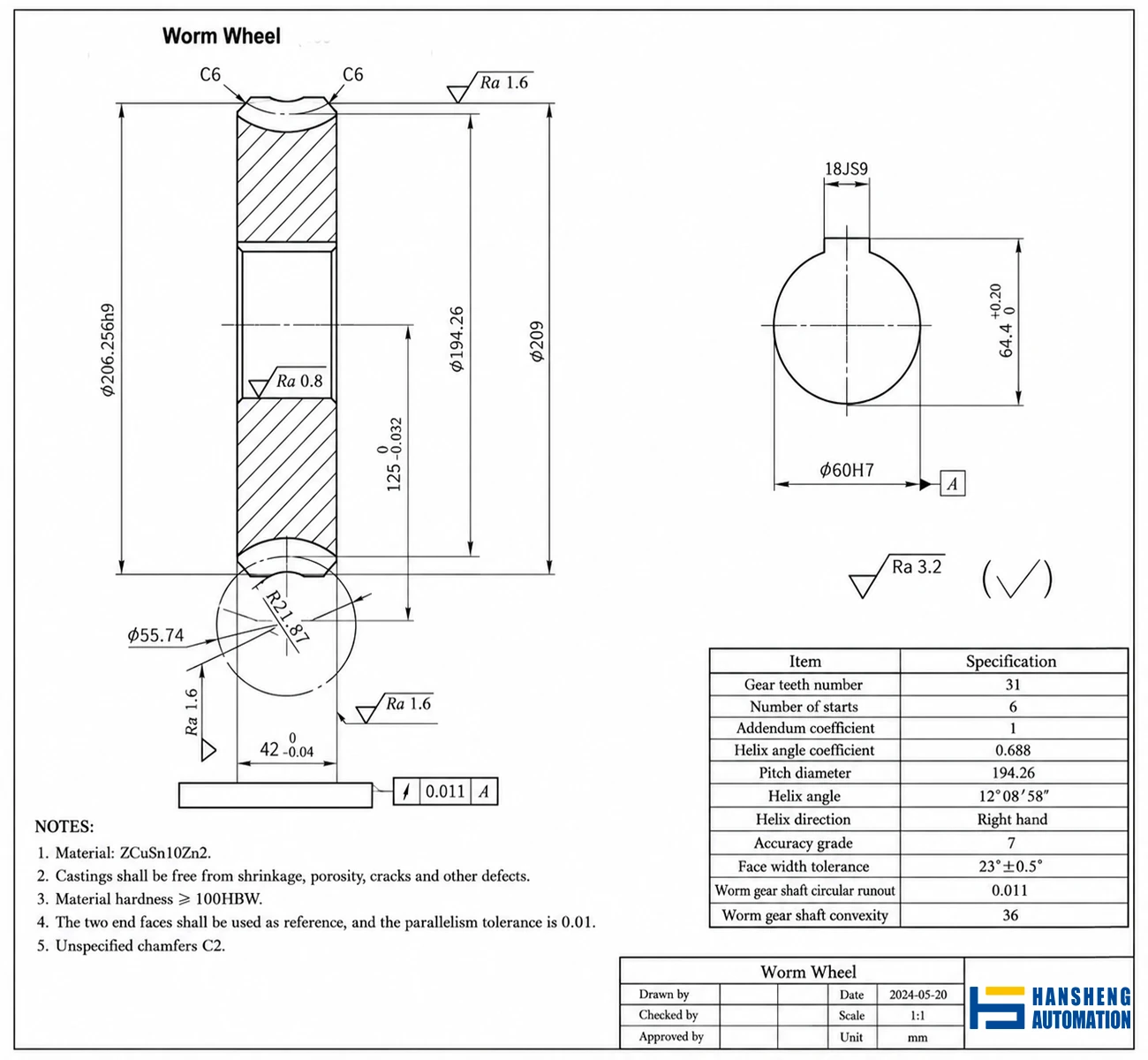
Engineering Drawing & Technical Requirements Analysis
Upon analyzing this internal engineering reference drawing, our engineering department identified the key technical parameters and processing constraints:
Material Specification: Cast Tin-Zinc Bronze (ZCuSn10Zn2), requiring a minimum hardness of >= 100 HBW and a casting structure completely free from shrinkage, porosity, or internal defects.
Critical Dimensional Tolerances:
- Φ60H7 Inner Bore: A high-precision fit requiring a surface finish of Ra 0.8 um.
- 18JS9 Keyway: Precision slotted keyway to ensure reliable shaft engagement.
- Throat Width (42 mm +0/-0.04 mm) and Parallelism of End Faces (<= 0.01 mm): These serve as the datum references for all subsequent gear-cutting operations.
Gear Geometry (Accuracy Grade 7): A 31-tooth, 6-start, right-hand helix worm wheel with a throat radius of R21.87 and a pitch diameter of 194.26 mm.
Process Strategy & Stress Relief
Worm wheel accuracy is heavily dependent on the precision of the gear blank. To ensure long-term dimensional stability and prevent distortion during final machining, we adopted a staged processing strategy:
- Rough Machining: Quickly remove bulk material to reveal the basic gear geometry.
- Artificial Aging (Thermal Stress Relief): Crucial for cast bronze parts to eliminate internal residual casting stresses.
- Finish Machining & CNC Hobbing: Finish the datum surfaces and cut the teeth only after the material structure has stabilized.
Step-by-Step Manufacturing Workflow
The table below outlines the precise machining sequence executed in our facility to manufacture this custom worm wheel:
| Operation | Step | Process Description | Equipment | Tooling & Inspection Gages |
|---|---|---|---|---|
| Op 10: Casting | – | Cast the ZCuSn10Zn2 raw blank. Perform visual and non-destructive testing to ensure a defect-free structure. | Foundry | Hardness tester |
| Op 20: Rough Turning | 1 | Initial Blank Preparation: Chuck the raw casting OD, face the first end. | Conventional Lathe | 45° Bent-shank tool, 90° Turning tool |
| 2 | Rough turn outer diameter to Φ211 mm (allowance for finish turning). | |||
| 3 | Reverse the blank, face the second end to achieve a total width of 44 mm. | |||
| 4 | Rough bore the inner hole to Φ58 mm. | Inside boring bar | ||
| Op 30: Heat Treatment | – | Artificial Aging: Apply thermal stress relieving to stabilize the bronze crystalline structure, preventing deformation in subsequent steps. | Heat Treatment Furnace | Temp. controllers |
| Op 40: Precision Turning | 1-4 | Chuck Φ209 OD. Finish face the right end (Width 43 mm, Ra 1.6 μm), finish bore Φ60H7 (Ra 0.8 μm), chamfer C6 OD and C2 ID. | CNC Lathe | 35° Indexable carbide inserts, Precision boring tool, Three-point internal micrometer |
| 5-9 | Reverse blank, clamp via the precision inner bore. Finish face left end to 42-0.040 mm (Ra 1.6 μm, ensuring parallelism ≤0.01 mm). Turn OD to Φ209 mm and profile the R21.87 throat radius (Ra 3.2 μm). | Radius tool, Profile gauge, Dial indicator | ||
| Op 50: CNC Hobbing | – | Gear Cutting: Align center height and center distance precisely. Hob the 31 teeth to meet Grade 7 Accuracy standards. | CNC Gear Hobbing Machine | Custom Hobs matching the 6-start mating worm |
| Op 60: Slotting | – | Keyway Machining: Slot the 18JS9 keyway (Ra 3.2 μm) into the Φ60H7 bore. | Slotting / Shaping Machine | Keyway broach/tool, Go/No-Go keyway plug gage |
| Op 70: Benchwork | 1-2 | Deburr tooth profiles and sharp edges; apply custom laser marking/part numbering. | Bench Workstation | Manual deburring tools, Laser marker |
| Op 80: Inspection | 1 | Metrology: Verify tooth dimensions, runout, and pitch circle tolerances. | Gear Measuring Center / CMM | Coordinate Measuring Machine |
| 2 | Contact Pattern Verification: Perform blueing/meshing tests with the mating master worm to verify actual contact area and ensure smooth drive rotation. | Roll Testing Fixture, Master worm shaft | ||
| Op 90: Packaging | – | Thoroughly clean the part, apply anti-oxidation wrapping, and pack in secure wooden crates for transit. | Packing Area | – |
FAQ
We accept a variety of standard engineering formats. For 2D drawings, we prefer PDF, DWG, or DXF formats (with complete dimensions, tolerances, and material specifications). For 3D models, we accept STEP (.stp), IGES (.igs), or solid parts files.
Yes, absolutely. Protecting our customers’ intellectual property is a fundamental policy at Hansheng Automation. We are fully prepared to sign a standard NDA before you share any drawings or technical specifications with us. All customer files are kept strictly confidential within our engineering department.
As a custom manufacturer, we offer highly flexible order volumes. We support single-piece (1 pc) prototyping for your R&D and testing phase, as well as small-to-medium batch production. Please note that set-up costs for gear machinery are relatively fixed, so unit prices are generally more economical for larger production batches.
Quality assurance is integral to our manufacturing process. Upon request, we provide a complete inspection package with your shipment, which typically includes:
– Material Mill Certificate (confirming bronze/steel composition)
– Dimensional Inspection Report (covering critical bore, throat, and keyway tolerances)
– Heat Treatment / Hardness Test Report (if thermal processing was applied)
– Gear Meshing & Contact Pattern Test Report
Lead times depend on the complexity of the gear geometry, material availability, and required post-processing (such as heat treatment or specialized grinding). Typically, prototype or low-volume orders take about 2 to 3 weeks, while medium-batch production runs take approximately 4 to 6 weeks. We will provide a reliable delivery schedule along with our official quotation.
We work with a wide range of industrial materials. For worm shafts, we commonly use carbon steel (such as 45#), alloy steels (like 40Cr or 20CrMnTi with carburizing and quenching), and stainless steel. For worm wheels, we offer various wear-resistant bronzes (Tin Bronze ZCuSn10Zn2, Aluminum Bronze), brass, cast iron, and high-strength engineering plastics like Nylon (POM).


