What is a Spline Shaft The Complete Analysis to Spline Types, Standards & Selection
Blog 2026-06-24
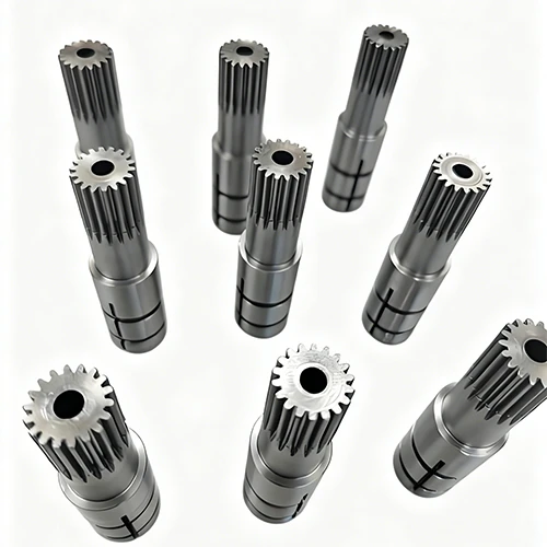
In high-torque or high-frequency reversing applications, a spline shaft offers a superior alternative to a standard single keyway, which often becomes the primary failure point. Under continuous reversing stress, keyways are prone to wallowing, key deformation, and torsional fatigue cracking originating at the sharp root corners.
To overcome these limitations, engineers turn to splined designs. A spline shaft carries a series of longitudinal teeth (splines) that engage matching grooves in a mating female component, transmitting high torque while maintaining angular alignment.
What is a spline? It refers to any individual ridge machined on the shaft (external spline) or inside the bore (internal spline). By distributing torsional load across multiple teeth—typically manufactured to standards such as DIN 5480 or ISO 4156—splines eliminate the localized stress concentration found in keyways, ensuring reliable, high-capacity power transmission.
Keyway vs. Spline Shaft: Why and When to Upgrade?
Under heavy torsional loads or abrupt start-stop cycles, a traditional keyway connection concentrates the entire driving force onto a single, narrow contact plane. On the shop floor, this localized pressure inevitably causes elastic deformation at the key seat, leading to micro-slip. Over time, fretting corrosion sets in, widening the clearance and introducing backlash. Under high speeds and reversing torques, the key eventually rolls, shears, or initiates fatigue cracks at the sharp root corners of the keyway.
To visualize the engineering differences, consider this mechanical comparison:
| Performance Metric | Traditional Keyway (Single/Double) | Spline Shaft |
|---|---|---|
| Load-Bearing Contacts | 1 or 2 localized keys | Multiple teeth (typically 6 to 40+) |
| Stress Distribution | Severe stress concentration at sharp corners | Uniform radial distribution across circumference |
| Backlash Control | Poor (widens over time under shock loads) | Highly precise (adjustable via clearance/interference fits) |
| Axial Slide Under Load | Highly restricted; prone to binding and galling | Smooth sliding enabled by balanced radial forces |
| Typical Failure Mode | Key shearing or shaft root torsional cracking | Gradual, predictable tooth surface wear |
Upgrading to a spline shaft design resolves these failure modes through three fundamental mechanical advantages:
- Equally Distributed Load : Spreading torsional force across multiple teeth reduces contact stress per tooth flank, allowing the assembly to handle higher peak torques and shock loads.
- Accommodating Axial Sliding While Rotating : For telescoping action under load (e.g., automotive drive shafts or PTO systems), splines enable axial sliding with minimal resistance; balanced radial forces virtually eliminate binding.
- Reduced Backlash and Enhanced Efficiency : High-precision manufacturing minimizes angular play, preventing rotational hammering during reversals and ensuring smoother transmission and longer system life.
The 4 Major Types of Spline Shafts (How they Differ)
Selecting the appropriate spline geometry is critical to matching the mechanical demands of your transmission system. While all splines transmit torque, their tooth profiles dictate how they distribute load, handle misalignment, and behave under dynamic stress.
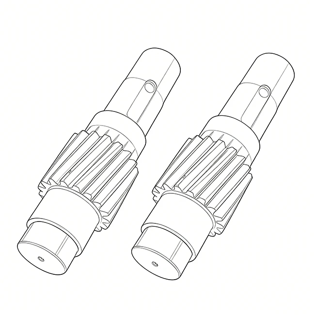
Parallel Key (Straight) Spline Shafts
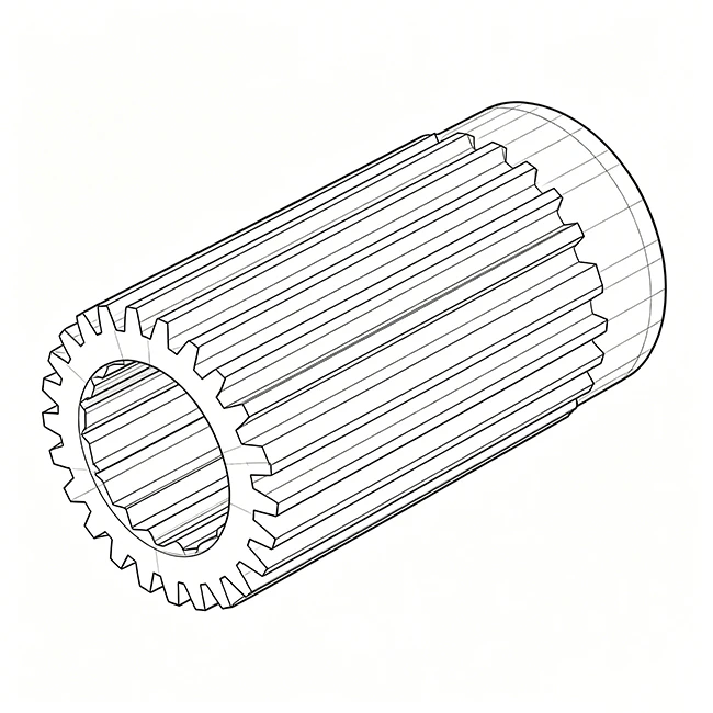
Defined by their square-toothed profile, parallel splines feature straight, parallel flanks. Because of their straightforward geometry, they are highly cost-effective and relatively simple to machine using standard milling or hobbing setups.
However, they have distinct physical limitations. Parallel splines exhibit high stress concentration at the sharp root corners and lack the ability to self-align under load. Consequently, they are typically restricted to low-to-medium speed, light-duty applications, or systems where the mating components only slide under static, non-torque conditions.
Involute Spline Shafts
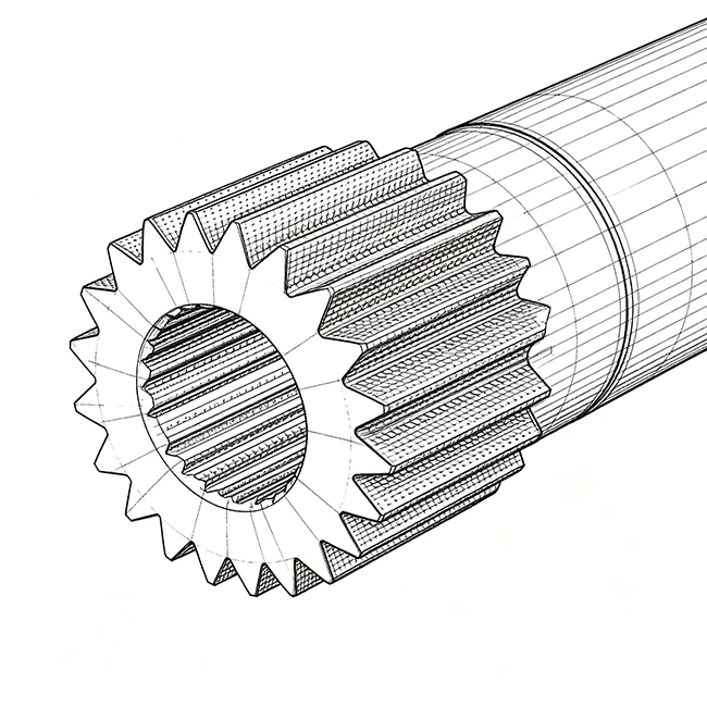
Unlike parallel keys, involute splines feature curved gear‑like teeth with standard 30° or 37.5° pressure angles, fully standardized under DIN 5480 and ISO 4156. Their progressive tooth profile ensures even pressure distribution across the entire flank as torque increases.
Under torsional load, the curved teeth generate balanced radial forces that self‑center the hub and shaft, eliminating eccentricity‑induced uneven loading and reducing fatigue wear. The absence of sharp root corners lowers notch sensitivity, making involute splines the standard choice for high‑speed, high‑torque drivetrains in aerospace, automotive, and industrial applications. For systems demanding minimal angular backlash, custom‑ground involute splines shafts are specified; Hansheng Automation manufactures these to ISO/DIN Grade 5 standards using gear skiving and precision grinding.
Serrated (Triangular) Spline Shafts
Serrated splines utilize straight-sided, non-involute teeth with a large included angle, typically 90°. Because the teeth are small and highly dense, this design offers a large contact area relative to the shaft diameter.
Serrated splines are generally not intended for sliding applications. Instead, they excel in static or indexing connections—such as steering columns, valve drives, and instrument linkages—where high static shear resistance and precise angular positioning are required.
Ball Spline Shafts
When a mechanism must slide linearly with ultra-low friction while simultaneously transmitting high rotational torque, ball splines are required.
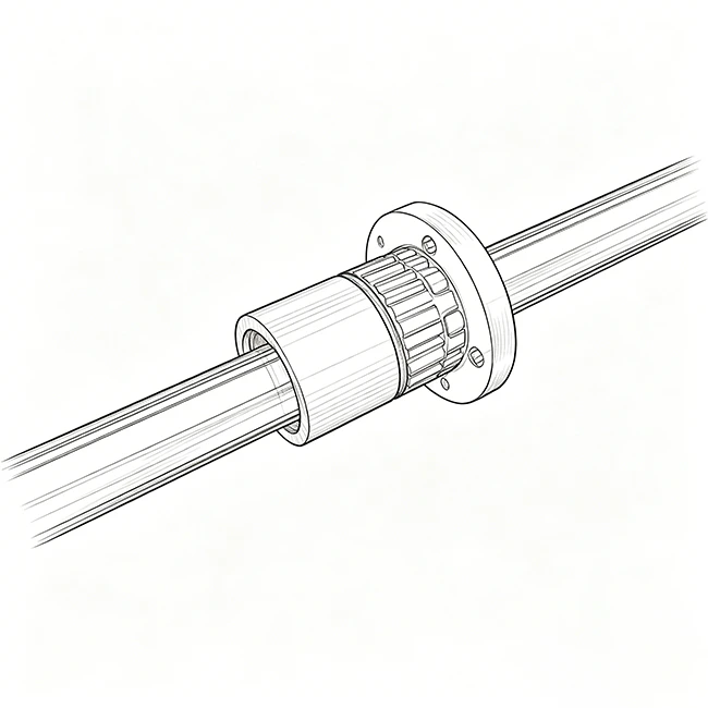
This specialized design features Gothic arch grooves ground along the shaft, allowing recirculating ball bearings inside the outer sleeve to roll smoothly. The rolling contact replaces sliding friction, providing near-zero backlash, extremely high positioning accuracy, and smooth axial travel under heavy radial and torsional loads. They are highly common in robotic arms, CNC spindle drives, and semiconductor handling equipment.
International Engineering Standards for Spline Shafts
In B2B procurement, strict international standards govern mechanical precision. For critical splined connections, matching the correct standard is vital for interchangeability, backlash control, and avoiding costly custom‑tooling. On the shop floor, machining a spline without first identifying the standard leads to immediate assembly failures, since mating hub and shaft must share identical tooth geometry, pressure angle, and tolerance class.

Engineers and buyers globally rely on three core standard systems to define their drawings:
DIN 5480 (German Metric Standard)
The most globally recognized metric standard for involute splines, using a reference‑diameter‑based system (e.g., DIN 5480 W 30 x 1.5 x 18 x 9g), 30° pressure angle with flat or fillet root, and modules from 0.5 to 10. It is the default choice for European machinery and precision automotive drivetrains.
ANSI B92.1 & B92.2M (American Standards)
ANSI B92.1 governs imperial involute splines by Diametral Pitch (DP) – e.g., 8/16, 16/32, 24/48 – with 30°, 37.5°, and 45° pressure angles. B92.2M defines metric module profiles.
ISO 4156 & GB/T 3478 (International & Chinese National Standards)
ISO 4156 is the unified international standard for metric involute splines, closely aligned with China’s GB/T 3478. Both use side‑fit geometries with 30°, 37.5°, and 45° pressure angles, widely applied in global supply chains to simplify tooling compatibility and reduce the need for proprietary hobs.
For custom DIN 5480 or ANSI B92.1 splines, contact our engineering team for drawing and tolerance review.
How to Measure and Identify a Spline Shaft: Counting Teeth & Dimensions?
When reverse-engineering a component on the shop floor or verifying a production run against a blueprint, identifying the exact spline count is your starting point. While it sounds simple, miscounting or incorrect measuring can lead to mismatched components and assembly delays.
Follow this straightforward procedure to determine the tooth count and key dimensions:
Step-by-Step Guide to Measuring Spline Shafts
- Step 1: Prep and Mark: Thoroughly clean any grease, rust, or debris from the spline area. Using a permanent marker or paint pen, mark the top of one spline tooth (the ridge) to serve as your starting reference point.
- Step 2: Count: Count the teeth sequentially in a clockwise direction, moving around the circumference until you return to your marked starting tooth.
Measuring Odd vs. Even Tooth Configurations
Once you have the tooth count, you will need to measure the Major Diameter (outer tip-to-tip) and Minor Diameter (inner root-to-root). The measurement technique depends heavily on whether your tooth count is even or odd:
Even Tooth Count
Because the teeth are positioned exactly 180 degrees apart, you can measure both diameters directly. Place the jaws of a calibrated vernier caliper or micrometer directly across opposing tooth tips for the Major Diameter, or opposing roots for the Minor Diameter.
Odd Tooth Count
On odd-tooth shafts, a tooth tip sits directly opposite a tooth space (root), making direct diametrical measurement with a standard caliper inaccurate.
- Direct Measurement: To estimate the Major Diameter, use a V-anvil micrometer, or measure from one tooth tip to the opposite space and apply a geometric correction factor.
- Precision Over-Pin Measurement: For high-tolerance quality control, use the “measurement over pins” method. Place two precision-ground pins of a specified diameter into opposing tooth spaces. Measure the outer dimension across the pins using an external micrometer, and then apply standard odd-tooth geometric formulas to calculate the precise pitch diameter.
Spline Shaft Material Selection & Heat Treatment for B2B Sourcing
While light‑duty products may use aluminum or plastics, high‑torque industrial transmissions demand high‑performance steel alloys. Incorrect material grade or heat treatment is the primary cause of catastrophic shear failure in industrial drives.
For robust B2B applications, material selection typically falls into two categories:
- Medium Carbon Steel (1045 / C45) – Best for standard‑duty, uniform‑load applications. Offers excellent machinability, cost‑effective processing, and responds well to localized surface hardening.
- Alloy Steels (4140, 42CrMo, 20CrMnTi) – Specified for heavy‑duty, high‑impact, or reversing drives. 42CrMo (AISI 4140) delivers exceptional fatigue strength and torsional resistance. For maximum wear resistance under severe shock loads, 20CrMnTi is the premier B2B choice due to its superior hardenability and core toughness.
The longevity of these steels depends entirely on the heat treatment process. A high-performance spline must possess a hard surface to resist flank wear, while maintaining a ductile core to absorb sudden torsional shocks. Two primary methods are utilized to achieve this:
- Induction Hardening: Applicable to 1045 or 42CrMo. Rapidly heats and quenches the spline teeth via induction, achieving a surface hardness of 50–55 HRC while the core retains its original ductility.
- Carburizing and Quenching: Designed for low‑carbon alloy steels like 20CrMnTi. Carbon is diffused into the surface layer at high temperature followed by quenching, producing a wear‑resistant case (58–62 HRC, depth 0.8–1.2 mm). This hardened shell, combined with a tough core, prevents brittle cleavage under peak overload conditions.
Custom Spline Shaft Manufacturing: Partner with a High-Precision Supplier
Selecting the correct spline profile, matching the appropriate international standard, and specifying proper heat treatment are the definitive steps to preventing premature drivetrain failure. But translating these engineering specifications into a precision component requires an equally capable manufacturing partner.
At Hansheng Automation, our decade of gear production experience bridges design and reality. We understand that optimal performance—whether for DIN 5480 or ANSI B92.1 profiles—hinges on maintaining tolerances down to ±0.005 mm. Leveraging advanced gear skiving, shaping, and CNC grinding, we routinely execute complex custom designs to ISO/DIN Grade 5 precision, ensuring reliable performance under the most demanding conditions.
If you are navigating custom spline geometry, tolerance classes, or seeking a reliable manufacturing partner, our technical team is ready to assist. Upload your 2D/3D drawings today for a comprehensive review, manufacturability analysis, and competitive quotation.
FAQ
A keyed shaft relies on one or two separate keys in machined slots, concentrating the entire torsional load on a narrow contact plane and creating severe stress concentration at keyway corners. In contrast, a spline shaft integrates multiple teeth (typically 6 to 40+) into its circumference, distributing load evenly over a larger area—increasing torque density, reducing wear, and enabling axial sliding under load.
Parallel splines have straight flanks and sharp root corners, which act as stress risers prone to fatigue, and lack concentric alignment. Involute splines feature a curved, gear‑like profile (typically 30° pressure angle) that generates balanced radial forces under load, pulling the hub into perfect alignment.
Accurate identification requires defining these parameters on your technical sheet:
Tooth count (z)
Major and minor diameters
Measurement system – metric (Module) or imperial (Diametral Pitch)
Pressure angle (commonly 30° for DIN 5480, or 30°/37.5°/45° for ANSI B92.1)
Pitch diameter verification via measurement over pins, checked against standard tables.
Yes for sliding splines; static (fixed) splines only need high‑pressure lubricant during assembly to prevent fretting and ease disassembly. Dynamic sliding splines require continuous lubrication—without it, reciprocating motion under torque causes friction, galling, rapid wear, and eventual binding.