Stainless Steel Helical Gears: A Complete 20Cr13 Manufacturing Guide
Blog 2026-08-01
This article details our precision manufacturing process for custom stainless steel helical gears—specifically a 20Cr13 component (Module 2, 49 teeth)—tracing its transition from forged blank to a finished ISO Class 7 gear.
Technical Drawing Analysis for Stainless Steel Helical Gears
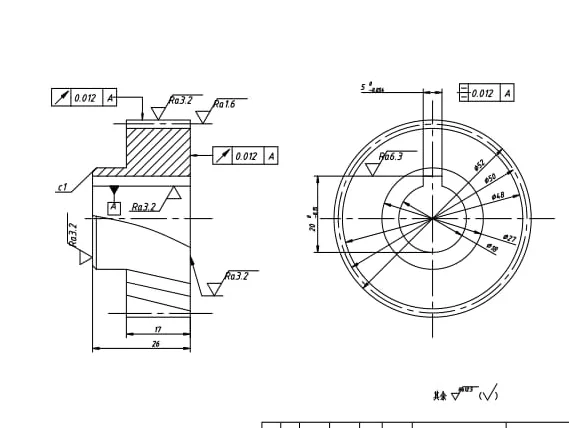
Material: 20Cr13 (AISI 420 / DIN 1.4021 equivalent), supplied in a quenched and tempered (Q&T) state. This treatment creates a uniform tempered sorbite microstructure that balances yield strength and impact toughness. As a result, the gear teeth withstand bending fatigue under moderate loads while maintaining necessary ductility during dynamic meshing.
To ensure operational reliability, the technical drawing specifies tight dimensional and geometric tolerances. Key manufacturing parameters include:
| Engineering Parameter | Specification |
|---|---|
| Material | 20Cr13 (Martensitic SS) |
| Heat Treatment | Quenched & Tempered (240–280 HBW) |
| Gear Geometry |
Modulus 2, 49 Teeth, Right-Hand
Pressure Angle αn = 20°
Helix Angle β = 13.93° (13°55’48”) Right-Hand
|
| Gear Precision | ISO / DIN Class 7 |
| Form & Position Tolerance |
• Bore Axis Perpendicularity to Datum A ≤ 0.012 mm
• Bore Radial Runout Fr ≤ 0.012 mm
|
| Surface Roughness |
• Flank: Ra 3.2 μm
• Datum A / Bore: Ra 1.6 μm
|
| Edge Requirements | Chamfer R1–R3 & sharp edge blunting |
Overcoming Hardships in 20Cr13 Helical Gear Machining
Machining martensitic stainless steel to tight tolerances requires solving two common shop-floor challenges: work hardening and thermal distortion.
1: Work Hardening & Built-up Edge
When machining 20Cr13, tough, gummy chips resist breaking, quickly leading to a built-up edge (BUE) on the cutter. This causes severe work hardening on the surface, accelerating tool wear and ruining the required Ra 3.2 µm flank finish. To overcome this, we use coated carbide tooling paired with high-concentration extreme-pressure (EP) coolant for targeted heat removal. Keeping cutting speeds between 30-50 m/min and maintaining a constant feed rate of f = 0.12-0.18 mm/rev (depth of cut ap = 0.2-0.3 mm) allows the tool to shear cleanly beneath the work-hardened layer rather than rubbing against it.
2: Precision Timing in the Stainless Steel Gear Heat Treatment Process
Where heat treatment is inserted into the process flow directly impacts final dimensional yield. Quenching and tempering after finish-turning or hobbing causes thermal distortion and surface decarburization, completely destroying 0.012 mm tolerances and ISO Class 7 accuracy. To maintain strict control, we follow a precise sequence: rough-machine the blank, execute Q&T to stabilize core hardness at 240–280 HBW, and then semi-finish turn to remove scale and distortion. Only after establishing this stress-relieved baseline do we proceed to final turning and gear hobbing.
9-Stage Process Route for Custom Stainless Steel Helical Gears
Producing high-precision stainless steel helical gears consistently requires a strictly controlled workflow that minimizes tolerance stack-up. Below is our standard 9-stage shop-floor process:
Step 1: Blank Preparation
We die-forge the raw stock to break down its as-cast microstructure and align grain flow. We then normalize the blank (≤200 HBW) to relieve forging stresses and improve its machinability.
Step 2: Rough Machining
We rough-turn the OD, bore, end faces, and steps, leaving a 2–3 mm stock allowance on all finish surfaces to accommodate thermal distortion during heat treatment.
Step 3: Quenching & Tempering (Q&T)
Parts undergo Q&T to achieve a uniform tempered sorbite structure and stabilize hardness at 240–280 HBW, verified via metallurgical batch testing.
Step 3: Quenching & Tempering (Q&T)
Referencing low-distortion surfaces, we turn away oxide scale and warped outer layers, leaving a 0.3–0.5 mm allowance per side for final turning.
Step 5: Finish Turning Datum A
Following the “datum-first” principle, we finish-turn the Φ32 bore and Datum Face A in a single setup. This ensures the bore axis and face are generated under the same rotational reference, eliminating angular deviation from repositioning.
We use a precision chuck with verified runout below 0.005 mm, with conservative cutting parameters: 120–150 m/min, feed 0.08–0.12 mm/rev, depth of cut 0.2–0.3 mm, using an AlCrN- or TiAlN-coated carbide insert for this hardness range (240–280 HBW). (CBN inserts are generally reserved for steels above 45 HRC and are not required here.)
The bore is finished to Φ32 H7, and Datum Face A is squared to the bore axis within 0.005 mm. In-process gauging—electronic plug gauge for the bore, dial indicator for face runout—confirms axial runout ≤0.012 mm and Ra 1.6 µm before the part proceeds.
Every downstream operation references this bore and face as the primary datums. Any error here propagates through broaching, hobbing, and inspection, making it impossible to recover the 0.012 mm tolerance or ISO Class 7 accuracy.
Step 6: Keyway Broaching/Slotting
Referencing the finished Φ32 bore, we broach the 8 mm keyway and flood high-concentration coolant throughout to counteract 20Cr13’s toughness, preventing tool chatter and edge chipping.
Step 7: Precision Gear Hobbing
We mount the workpiece on an expanding hydraulic arbor inside the finished Φ32 bore, exerting uniform radial pressure to eliminate clearance. Datum Face A is pulled flush against the arbor flange, ensuring perpendicularity between the gear axis and hob feed. This dual-datum fixturing holds total indicated runout at the pitch diameter to ≤0.010 mm—a level consistently achieved on our Ningjiang YK3610IV CNC hobbing machine, whose rigid spindle and thermal stability ensure repeatability across production runs.
We use a PVD-coated carbide hob (TiAlN or AlCrN) for martensitic stainless steel. Cutting parameters distinguish roughing from finishing: roughing at 45–50 m/min, depth of cut 1.5–2.0 mm, feed 0.12–0.18 mm/rev; finishing at 30–35 m/min, depth 0.2–0.3 mm, feed 0.08–0.10 mm/rev. High-pressure (50–60 bar) EP oil is directed at the cutting zone to flush chips and suppress heat.
In-process inspection every 3–5 parts checks profile, lead, and pitch deviations against ISO Class 7 limits. Typical measured values for this gear geometry: fₚₜ ≤ 5 µm, Fα ≤ 6 µm, Fβ ≤ 6 µm, all well within Class 7 tolerance bands. If deviation trends appear, we index or replace the hob and adjust machine offsets in real time.
Step 8: Deburring & Edge Blunting
We clear burrs from tooth tips, bore shoulders, and keyway edges, applying R1–R3 chamfers to unspecified corners. We also carefully protect flanks during deburring to prevent nicks or metallic debris from affecting gear meshing.
Step 9: Final Inspection
Hardness is verified via batch sampling per heat treatment lot. Every finished gear then undergoes 100% dimensional and geometric inspection (bore runout, concentricity, tooth profile, lead, and pitch) prior to approval.
Quality Assurance for 0.012mm Tolerance Helical Gears
Maintaining ≤0.012 mm total runout and concentricity across production runs requires eliminating all locating play during machining and inspection.
Zero-Error Fixturing Strategy
Standard rigid arbors rely on clearance fits, introducing play that can swallow most of a 0.012 mm tolerance budget. To eliminate eccentricity between the pitch circle and rotational axis, we utilize a dual-datum fixture: an expanding hydraulic arbor exerts uniform radial pressure inside the Φ32 bore, while axial clamping seats Datum Face A flush against a ground reference surface. This eliminates play and guarantees perpendicularity, isolating gear cutting from fixture error.
Full Inspection Protocol
- Hardness Testing: 100% batch testing confirms 240–280 HBW core hardness before finish hobbing.
- Gear Profile Inspection: Tooth profile, lead, and pitch deviations are measured on a CNC gear measuring center to verify ISO Class 7 compliance.
- Geometric Tolerances: Bore runout and concentricity relative to Datum A are verified to stay within ≤0.012 mm.
- Surface Roughness Verification: Stylus profilometers confirm flank roughness (Ra 3.2 µm) and bore/datum roughness (Ra 1.6 µm).
Exception Protocols: Incoming hardness outside 240–280 HBW triggers re-tempering or rejection. Hob wear is monitored via in-process inspection; when deviation trends approach 80% of ISO tolerance, the hob is indexed or replaced. Thermal stability on the hobbing machine is maintained through a shift-start warm-up cycle and ambient temperature control.
Conclusion: Partner with Us for Custom Stainless Steel Helical Gears
Manufacturing high-precision stainless steel helical gears demands a proven, repeatable process. Our workflow effectively controls 20Cr13 work hardening, eliminates thermal distortion through proper heat treat sequencing, and holds tight 0.012 mm tolerances for ISO Class 7 hobbing.
Our quality inspectors perform 100% dimensional and tooth profile verification on every production batch. We provide Material Test Reports (MTR), heat treatment certificates, and CMM gear measurement charts upon request.
FAQ
20Cr13 is a standard martensitic stainless steel equivalent to AISI 420 (USA), DIN 1.4021 / X20Cr13 (Europe), and JIS SUS420J1 (Japan).
Performing Q&T (240-280 HBW) on the rough blank prevents severe thermal distortion from ruining the final 0.012 mm tolerance and ISO Class 7 accuracy. Subsequent semi-finish turning fully removes the oxidized outer layer.
We use coated carbide tools with positive rake geometry, maintain steady feed rates to prevent rubbing, and flood the cutting zone with high-pressure EP coolant to suppress heat generation.
Standard production lead times are typically 3–5 weeks, depending on batch size, raw material availability, and specific secondary processing needs. For prototype testing or urgent replacement requirements, we offer expedited production schedules.
We support both prototype development and mass production. Our MOQ starts from 1 piece for custom prototypes, with volume pricing applied for batch production runs.
Yes. We offer full custom gear manufacturing based on your technical drawings or reverse-engineered sample parts, accommodating non-standard modules, custom pressure angles, and special bore geometries.