Why a Larger Gear Module Is Not Always Better
Blog 2026-09-04
Increasing the gear module does not automatically improve a design. When center distance or housing space is fixed, a larger module forces a lower tooth count. Fewer teeth reduce the contact ratio (fewer teeth in mesh at the same time), which leads to rougher running, more noise, and higher gear vibration.
To keep the contact ratio high, select as many teeth as practical while staying within bending fatigue limits:
- Enclosed drives typically run with 20 to 40 teeth on the pinion.
- Open drives run lower, usually 17 to 20 teeth.
- The pinion tooth count must stay high enough to prevent undercut (at least 17 teeth for standard 20-degree full-depth profiles).
- Mating gears should ideally have coprime tooth counts so wear spreads evenly across all teeth over time.
- Tooth numbers must also align so the resulting center distance rounds cleanly to a standard nominal value.
Principles of Module Selection
The general rule is to pick the smallest module that still satisfies tooth bending fatigue strength. Calculations usually follow one of two paths based on tooth hardness:
Hardened gears: Tooth root breakage is the main failure risk. Calculate the required module directly using the tooth root bending fatigue formula, compare the result to the standard module series, and round up to the next standard size. Then run a contact fatigue check to confirm capacity.
Soft-tooth gears: Pitting is the main failure risk, so initial sizing starts from contact fatigue. First, calculate the required pinion pitch diameter (d). Choose a tooth count (z) between 20 and 40, then calculate the module using m = d/z. Round this up to the nearest standard module, and finish by checking bending fatigue strength.
Standard Module Conventions
Standard module series exist so parts can be cut with standard tooling and measured with standard gauges.
For helical gears, geometry splits into normal module (mn), transverse module (mt), and axial module (mx). Each equals the corresponding pitch divided by π, expressed in millimeters. Tooling matches the normal module (mn), which is the standard value.
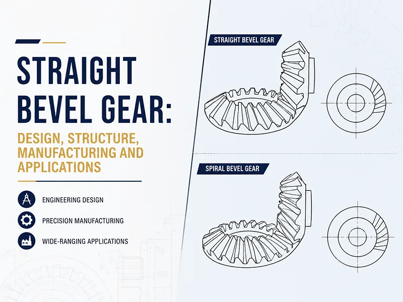
Straight bevel gear teeth taper along their face width. They use the large-end module (me) as the standard reference, alongside the mean module (mm) and inner module (mi).
Standard cutting tools, such as hobs and shaper cutters, are made to these metric module values. The same module series defines tooth geometry across worm drives, ratchets, gear couplings, and metric involute splines.
FAQ
Not in every case. A larger module thickens the tooth root, which increases bending strength. However, if center distance is fixed, a larger module forces a lower tooth count. This reduces the contact ratio (fewer teeth sharing the load simultaneously), which raises dynamic impact loads, accelerates pitting, and produces more noise.
Dropping below 17 teeth on a standard spur gear causes tooth root undercut during machining, which severely weakens the root. Even with profile shifting, very low tooth counts reduce the contact ratio close to 1.0, meaning single teeth take the full shock load rather than sharing it with adjacent teeth.
Choose a smaller module when low noise, smooth motion, and compact size are primary goals, such as in high-speed gearboxes and enclosed precision drives. A smaller module allows more teeth inside the same pitch diameter, increasing the contact ratio and reducing surface sliding velocity.
Module (m) is the metric standard, defined as reference pitch divided by π (in millimeters). Diametral Pitch (DP) is the imperial standard, defined as the number of teeth per inch of pitch diameter. They relate through the formula: m × DP = 25.4.