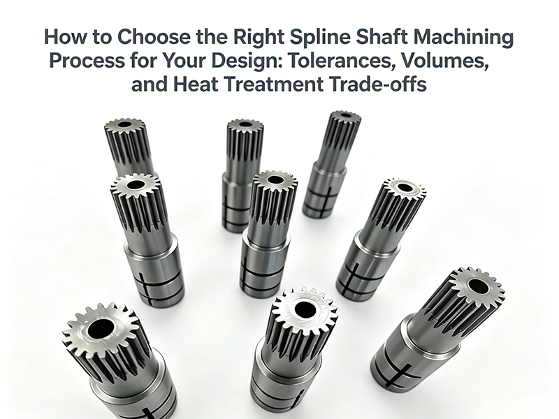
Rectangular Spline Shaft Manufacturing: Drawing Analysis, Machining Process & Inspection
Blog 2026-07-13
The standard spline shaft manufacturing process for a rectangular spline shaft typically follows a sequential route: quenching and tempering (Q&T), rough and finish turning, outer diameter (OD) grinding, spline milling, and final inspection. To meet the demanding tolerances of a large-diameter centered spline shaft, the machining process utilizes dual center holes as a unified positioning datum throughout the key operations.
Using an internal case study from Hansheng Automation, this article walks you through the entire lifecycle of rectangular spline shaft production—from drawings to machining and final warehousing.
Learn about the relevant rectangular spline sleeve manufacturing process.
Drawing Analysis
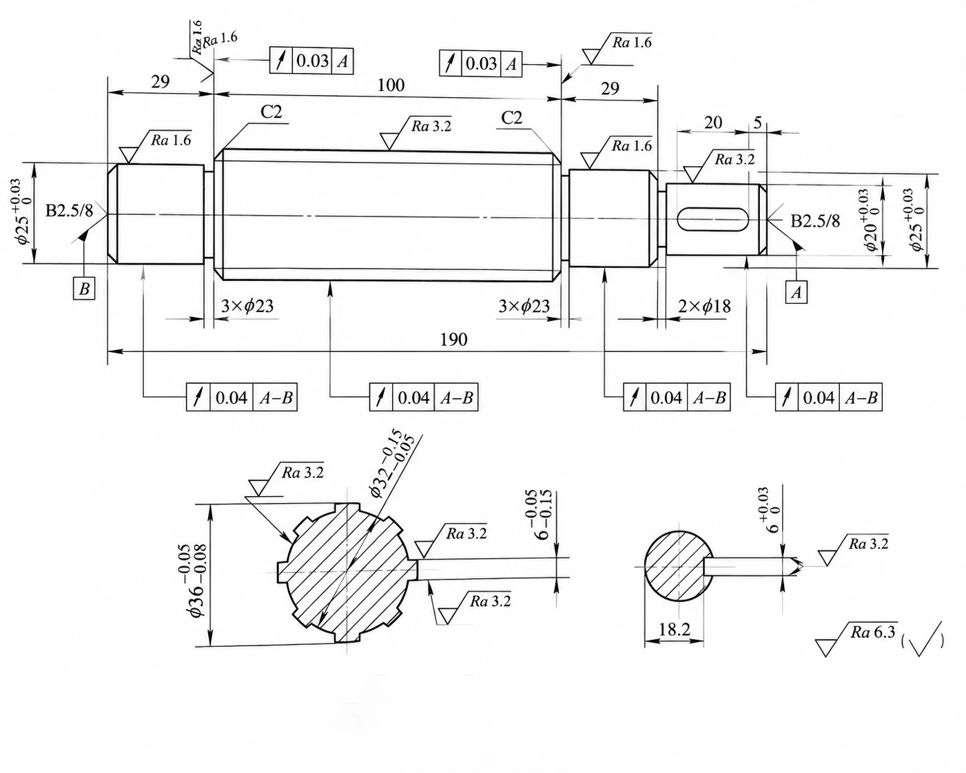
Based on the technical drawing, this part can serve as both a stepped shaft and a rectangular spline shaft. Below are the key specifications detailed in the blueprint:
| Parameter | Specification | Engineering Significance |
|---|---|---|
| Material | 45 Steel | A medium-carbon steel selected to provide an optimal balance of strength, toughness, and machinability. |
| Heat Treatment | 28–32 HRC | Quenching and tempering (Q&T) is specified to enhance core mechanical properties while maintaining a hardness range suitable for subsequent machining. |
| Spline Centering | Large-diameter centering | The outer diameter (OD) of the spline serves as the primary locating surface during assembly, dictating the manufacturing sequence. |
| Spline Outer Diameter (OD) | φ36 -0.05 / -0.08 mm | A tight dimensional tolerance required to ensure a precise, functional fit with the mating internal spline. |
| Radial Runout | ≤ 0.04 mm | Limits the coaxial deviation of the spline OD and the stepped journals (φ25 mm and φ20 mm) relative to the common axis. |
| Axial Runout (End Face) | ≤ 0.03 mm | Controls the perpendicularity of the spline end faces to minimize axial misalignment and vibration under thrust loads. |
Critical Manufacturing Interpretations
Unified Positioning Datum: To satisfy the strict radial runout tolerance of ≤ 0.04 mm across the multiple stepped journals and the spline OD, the dual center holes on both ends of the shaft must serve as both the design and process datum. Machining processes must utilize these center holes for positioning to avoid datum-shift errors.
Mating Surface Preparation: Because the design specifies large-diameter centering, the φ36 -0.05/-0.08 mm outer diameter acts as the locating interface. Consequently, the OD must be finish-ground to its final tolerance prior to milling the spline teeth to guarantee both dimensional accuracy and coaxiality.
All spline dimensions and inspection procedures follow GB/T 1144-2001, China’s national standard for straight-sided splines, which is technically non-equivalent to ISO 14:1982. DIN 5464 is also available upon request for customers who reference European standards.
Why Large-Diameter Centering?
From an assembly and manufacturing perspective, large-diameter centering designates the spline’s outer diameter (OD) as the primary functional locating surface. This design choice dictates a specific machining sequence for two critical engineering reasons:
Ensuring Grinding Stability
Grinding the spline OD before milling the teeth ensures a continuous cylindrical surface. If the teeth were milled first, grinding the OD afterwards would result in an interrupted cut. Interrupted grinding induces micro-vibrations, accelerates grinding wheel wear, and makes it extremely difficult to maintain the required tight dimensional tolerance (ϕ36 -0.05/-0.08 mm).
Coaxiality and Runout Control
Grinding the continuous cylinder first using the dual center holes as a datum establishes a highly precise concentric reference. This sequence minimizes cumulative radial runout, ensuring that the functional locating surface satisfies the strict ≤ 0.04 mm runout tolerance relative to the common axis.
The Step-by-Step Rectangular Spline Shaft Manufacturing Process
Below, we break down how a raw steel bar is processed into a high-precision rectangular spline shaft through the following six stages:
1: Material Preparation and Thermal Conditioning (Steps 1 to 2)
- Raw Stock Cutting: Standard diameter 40 mm x 200 mm medium-carbon 45 steel bar stock is sawed to length using a band sawing machine.
- Quenching and Tempering (Q and T): The raw blank undergoes a thermal treatment cycle to achieve a uniform core hardness of 28 to 32 HRC. This hardness range optimizes the tensile strength and toughness of the shaft while preserving its machinability for subsequent metal-cutting operations.
In actual production, we usually reserve sufficient grinding allowance after quenching and tempering because 45 steel shafts with multiple diameter steps tend to exhibit slight bending distortion after heat treatment. Grinding after heat treatment is therefore critical for restoring the common-axis accuracy.
2: Datum Establishment and Rough Turning (Steps 3 to 5)
- Face Preparation and Center Drilling (End A): We start by chucking one end of the workpiece in a CA6140 engine lathe. The exposed end face is faced flat (clean-up cut) to establish a perpendicular reference, and then we drill a Type B2.5/8 center hole.
- Face Preparation and Center Drilling (End B): After reversing the shaft in the chuck, we turn the second face to achieve the precise total length of 190 mm, followed by drilling the opposing Type B2.5/8 center hole.
- Rough Turning of Stepped Diameters: With the newly drilled dual center holes as the unified positioning datum, we mount the shaft between centers. All cylindrical stepped sections are rough-turned, leaving a 2.0 mm radial allowance and a 2.0 mm axial allowance for finish machining. (The operator performs this operation in a single setup to maintain concentricity.)
3: Finish Turning and Groove Machining (Step 6)
With the bulk of the raw material removed, finish turning prepares the minor features and defines the grinding margins.
- Finish Turning: We complete the finish turning of all outer diameters in a single setup between centers on the CA6140 lathe to ensure concentricity. A precise 0.4 mm grinding allowance is reserved on the ODs for final abrasive finishing.
- Grooving and Chamfering: We cut the specialized features during this same setup without repositioning the workpiece. These include two 3 mm × diameter 23 mm undercuts, one 2 mm × diameter 18 mm relief groove, and chamfers at C2.2 and C0.7.
4: High-Precision Cylindrical Grinding (Step 7)
- Cylindrical Grinding: We mount the shaft between centers on an M1432A cylindrical grinding machine. Both rough and finish grinding pass over all OD stepped sections to bring them within the final drawing tolerances.
- Face Grinding: Next, we grind the end faces of the spline section to achieve the exact 100 mm functional length. By grinding the OD before spline cutting, we ensure a continuous, stable grinding surface—preventing wheel chatter and securing the φ36 mm OD (tolerance -0.05/-0.08 mm) to strict coaxiality requirements.
5: Spline and Keyway Milling (Steps 8 to 10)
Once the grinding operations establish a precise cylindrical surface, the rotational drive features are machined.
Spline Milling: The shaft is mounted on an X6132 horizontal milling machine using a “one-chuck, one-center” configuration (clamped in a dividing head chuck and supported by a tailstock center). The operator rough and finish mills the 6 x 8 mm spline to a tolerance of -0.05 / -0.15 mm, while holding the minor diameter to diameter 32 mm (tolerance -0.05 / -0.15 mm).
How We Control Indexing and Symmetry During Spline Milling
When machining rectangular splines on a conventional milling machine, we generally perform rough milling first and leave a small finishing allowance. This reduces cutting force during indexing and helps improve the symmetry of the spline teeth.
- Scribing Keyway Lines: The shaft is moved to a marking station where layout lines are scribed for the 6 mm keyway to guide the subsequent milling operation.
- Keyway Milling: Re-clamped using the “one-chuck, one-center” setup on an X5030A vertical milling machine, the 6 mm keyway (tolerance +0.03 / 0 mm) is milled to a final depth of 18.2 mm.
6: Final Quality Inspection and Storage (Steps 11 to 12)
Before the finished rectangular spline shaft is cleared for assembly or shipment, it must undergo strict quality validation.
- Dimensional and Tolerance Inspection: The component is evaluated against all blueprint requirements. Key inspection parameters include verifying the diameter 36 mm spline OD, checking the keyway symmetry, and measuring radial and axial runouts relative to the common axis.
- Rust Prevention and Storage: Upon passing all metrological tests, the spline shaft is cleaned, treated with rust-preventative oil, and moved to warehouse storage.
Analysis of Manufacturing Challenges in Rectangular Spline Shaft Machining
In practical production, manufacturing high-precision rectangular spline shafts often involves unforeseen issues not shown on the blueprints. The following are the real-world problems we faced and how we resolved them. We hope these insights serve as a useful reference if you run into similar challenges.
Controlling Heat Treatment Distortion
During the quenching and tempering (Q&T) phase of the 45 steel shaft, metallurgical phase transformations and thermal stresses inevitably cause slight bending and dimensional warping, particularly on stepped shafts.
The Control: The manufacturer executes the thermal cycle early in the manufacturing sequence. Machinists perform all critical rough turning, finish turning, grinding, and milling operations after Q&T. Executing these precision machining steps after the metallurgical structure has stabilized allows operators to completely machine out any thermal distortion, restoring common-axis accuracy.
Achieving Large-Diameter Centering Accuracy
The Problem: For a large-diameter centered spline shaft, the outer diameter (OD) acts as the primary functional locating surface during assembly. Maintaining the tight diameter 36 mm (tolerance -0.05 / -0.08 mm) specification on a turned surface is insufficient for high-precision fits.
Solution: High-precision cylindrical (OD) grinding is integrated into the workflow prior to milling the spline teeth. Grinding the OD while the cylinder is still continuous ensures superior circularity and surface finish, preventing the wheel chatter and geometric errors associated with interrupted grinding on pre-milled teeth.
Minimizing Spline Indexing (Equal-Division) Error
The Problem: Variations in the angular spacing of the spline teeth prevent uniform load distribution across all six keys during operation. This unequal loading leads to concentrated stress, localized wear, or assembly failure with the mating internal spline.
Solution: In low-volume production using conventional horizontal milling machines, angular errors are minimized by using a high-precision universal dividing head and a rough-and-finish milling sequence. For mass production, a dedicated spline hobbing or milling machine is utilized to ensure automatic, consistent indexing and high geometric reproducibility.
Ensuring Keyway and Spline Side Symmetry
The keyway and spline teeth must be perfectly symmetrical relative to the shaft’s central axis. Any angular or lateral offset reduces the load-bearing contact area and compromises the strength of the drive connection.
Solution: This is managed by executing a rigorous setup alignment and using a dial indicator for verification. Before the final finishing pass of the spline and keyway milling, a dial indicator is used to re-check the alignment and symmetry of the features relative to the reference axis, allowing for micro-adjustments prior to final machining.
Inspection Method for Rectangular Spline Shafts
Verify that the finished rectangular spline shaft complies with all specified geometric and dimensional tolerances, focusing primarily on radial runout, axial runout, and feature symmetry relative to the common axis.
Runout Verification Setup
The shaft is mounted between centers on a runout tester. Using the dual center holes as the physical reference axis, a dial indicator is used to verify the runout of the following critical features:
- Spline End Faces: Tested for axial runout (tolerance limit of 0.03 mm) to ensure perpendicularity.
- Spline Outer Diameter (OD): Tested for radial runout (tolerance limit of 0.04 mm) to confirm the concentricity of the functional locating surface.
- Stepped Journals: The two diameter 25 mm journals and the diameter 20 mm journal are tested for radial runout (tolerance limit of 0.04 mm) to prevent vibrational and alignment issues during operation.
Dimensional and Symmetry Verification
- Feature Dimensions: The spline outer diameter (diameter 36 mm), minor diameter (diameter 32 mm), and key width are measured using a vernier caliper or micrometer.
- Feature Symmetry: The symmetry of the keyway and spline teeth relative to the shaft axis is checked on a surface plate using a dial indicator to detect any angular or lateral offsets.
- Batch Inspection: While manual instruments (micrometers, dial indicators, and runout testers) are standard for prototypes and low-volume batches, mass-production quality control utilizes comprehensive spline go/no-go ring gauges to verify the overall composite fit.
FAQ
Rectangular splines (straight-sided) feature parallel keys and rely on major- or minor-diameter centering. They are easy to manufacture with standard cutters but have high stress concentrations at the roots.
Involute splines have curved, gear-like teeth. They offer self-centering under torque, higher load capacity, and lower stress concentration, making them ideal for high-speed and high-torque applications.
For major-diameter fit splines, the outer diameter (OD) serves as the locating surface. Grinding the OD first ensures a continuous cylindrical surface. Grinding after milling creates an interrupted cut, leading to wheel vibration (chatter), accelerated wheel wear, and poor dimensional accuracy.
Yes. Rectangular splines can be cut on a horizontal milling machine using a dividing head and a profile cutter. This setup is cost-effective for prototypes or low-volume repairs, but unsuitable for mass production due to slow cycle times, manual indexing, and cumulative indexing errors.
Mount the shaft between centers on a runout tester, using the center holes as the reference axis. Position a dial indicator against the target surface (spline OD, journals, or faces) and rotate the shaft 360 degrees. The maximum variation indicates the Total Indicator Runout (TIR), which must meet drawing specs (typically <=0.04 mm radial and <=0.03 mm axial).
A quenched and tempered (Q&T) hardness of 28 to 32 HRC is recommended. This range balances the core toughness and fatigue strength needed for torque loads, while keeping the steel machinable for turning, milling, and grinding without causing excessive tool wear.
About Hansheng Automation
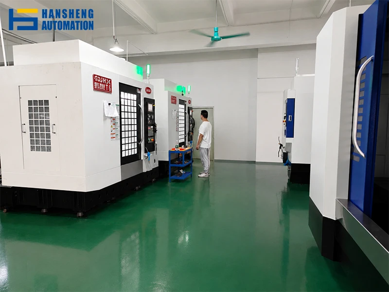
Hansheng Automation specializes in high-precision engineering and manufacturing, delivering end-to-end component solutions from rapid prototyping and low-volume production to scalable manufacturing. We integrate advanced technical capabilities, including multi-axis CNC machining, high-precision grinding, and metallurgical heat treatment, to transition complex CAD designs into production-ready mechanical parts.
With over 10 years of industry experience, we have served more than 1,000 clients worldwide. We have built deep expertise in providing proven, high-tolerance component solutions across demanding fields, including robotic joints, precision speed reducers, tobacco packaging machinery, and industrial automation. Our engineering-first approach ensures that every component is optimized for mechanical stability, wear resistance, and strict dimensional compliance.