Integrated Ring Gear in Motor Housing: Manufacturing Challenges for Humanoid Robot Joints
Blog 2026-06-04
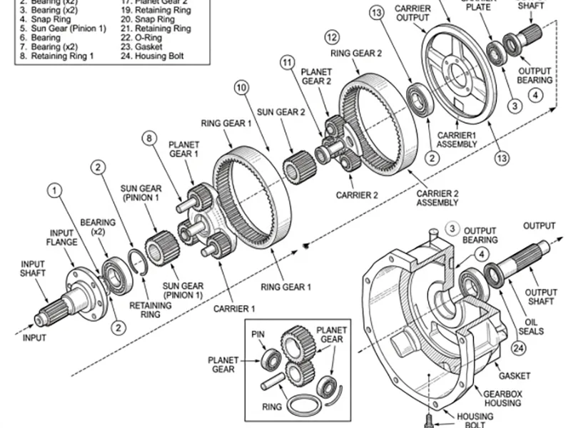
The ring gear is the outermost fixed element in a planetary gear system. In most gearbox designs, it is a discrete component — machined separately, then pressed or bolted into a housing. Humanoid robot joints operate under different constraints.
Joint actuators for humanoid robots must fit inside a limb structure, survive repetitive impact loads, and keep total mass low enough that it doesn’t compromise the robot’s dynamic balance. These requirements push engineers toward integration: rather than housing a separate ring gear, they machine the internal teeth directly into the motor housing wall. One component disappears. The interference fit between ring gear and housing disappears with it. Axial length drops.This is the integrated ring gear approach.
The tradeoff is manufacturing complexity. Internal tooth cutting in a structural housing is fundamentally different from hobbing an external gear. This article works through each of those challenges: process selection for internal gear cutting, geometric accuracy requirements, material and heat treatment tradeoffs, etc.
Why Humanoid Robots Are Pushing the Limits of Gear Integration
From Modular Gearboxes to Integrated Ring Gear Motor Housing: How Humanoid Joint Design Has Shifted
Early humanoid robot joints borrowed directly from industrial robotics: a servo motor coupled to a standalone gearbox, with encoders and drive electronics mounted separately. This modular approach made sourcing straightforward, but it accumulated cost in axial length, connector count, and assembly interfaces.
The commercial humanoid programs of the past several years — driven by mass-production targets rather than laboratory demonstration — have moved decisively toward integrated joint modules. Motor, transmission, encoder, and driver electronics are designed as a single unit from the outset.
Integrating the ring gear into the motor housing is one step in that direction.
| Parameter | Modular Design | Integrated Design |
|---|---|---|
| Ring gear mounting | Separate component, press-fit or bolted | Internal teeth machined into housing bore |
| Axial length contribution | Housing wall + ring gear wall thickness | Housing wall only |
| Assembly interfaces | Motor housing ↔ ring gear ↔ gearbox housing | Motor housing only |
| Tolerance stack-up sources | 3–4 interfaces | 1–2 interfaces |
| Component count (transmission) | Higher | Reduced by 1–2 parts |
Note: The numbers in each cell will vary by design. The directional trend does not.
What “Integrated Ring Gear” Actually Means in This Context
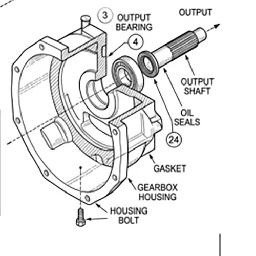
For the purposes of this article, it refers to a specific manufacturing decision: the internal gear teeth that serve as the ring gear in a planetary stage are cut directly into the bore of the motor housing, rather than into a separate ring gear blank that is subsequently installed into the housing.
This means the motor housing must simultaneously function as a structural enclosure, a bearing carrier, a stator mount, and a precision gear component. Each of those functions places its own demands on geometry, surface finish, and material. Managing them in a single part is the central manufacturing challenge.
Why is this design chosen?
- Reduced axial length
- Elimination of one interference fit
- Reduced tolerance stack-up
- Mass reduction
Of course, this requires first overcoming manufacturing difficulties; otherwise, those advantages disappear / cannot be realized.
Manufacturing Challenges of the Planetary Ring Gear Integrated Housing
Internal Gear Cutting Processes for Ring Gear Motor Housing
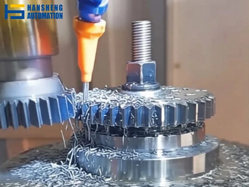
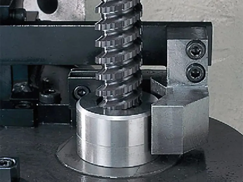
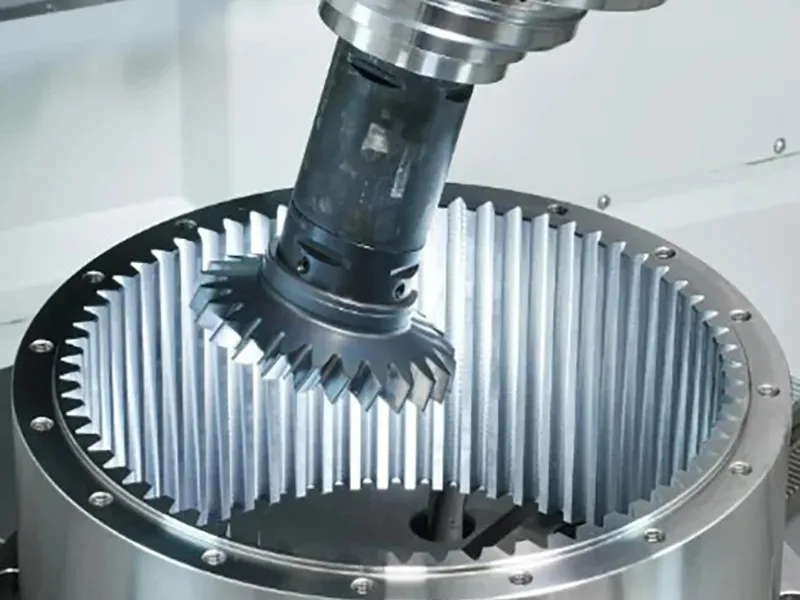
The hob cannot enter a bore. For internal ring gears, three alternative processes exist, each with different capabilities and costs.
Gear Shaping uses a reciprocating cutter that plunges axially into the bore. It is flexible — the same machine handles both internal and external gears — and tooling is relatively accessible. The limitation is speed: the reciprocating stroke is inherently slower than continuous cutting, and achievable accuracy typically lands at G class 7–9. For a precision robot joint, class 7 is marginal; class 6 or better is preferred.
Gear Broaching pulls a multi-tooth broach through the bore in a single pass, producing the full tooth form at once. It delivers accuracy (GB class 8–11 in finishing passes) and excellent surface finish, but it is fundamentally a high-volume process. Broach tooling is expensive, application-specific, and economically justified only when part counts are large. It also requires through-bores and sufficient bore length for the broach to clear — geometry constraints that integrated motor housings frequently violate.
Power Skiving is a continuous cutting operation in which a skiving cutter rotates in a synchronized, crossed-axis relationship with the workpiece. This delivers cutting speeds that approach hobbing, with the bore-access capability of shaping. Achievable accuracy reaches GB class 5–7, which is appropriate for precision robotic joints.
| Process | Geometry | Accuracy (GB) | Volume suitability |
|---|---|---|---|
| Shaping | Internal & external | 7-9 | Low-medium |
| Broaching | Internal (through-bore) | 8-11 | High |
| Power Skiving | Internal & external | 5-7 | Medium-high |
For integrated ring gear motor housings — small-to-medium batch, high accuracy, complex bore geometry — power skiving is currently the most capable process.
Concentricity and Coaxiality
Three cylindrical features must share a common axis within tight tolerance: the stator bore, the bearing seats, and the ring gear pitch cylinder. Misalignment between any two of these produces eccentric planet orbits, uneven tooth loading, and repeatable position error at the joint output.
For precision robotic joints, concentricity between these features is typically held to ≤0.005 mm. At a ring gear pitch diameter of 60 mm, a concentricity error of 0.01 mm produces a positional error of approximately 1.1 arc-minutes at the output — before any other error sources in the transmission chain are considered.
Achieving this requires that all three features are machined in a single setup, or that datum transfer between setups is verified and controlled. Re-chucking the part between operations introduces positioning error that cannot easily be recovered by adjustment.
Verifying ring gear pitch cylinder concentricity relative to external bearing seats requires either a gear measuring center with internal probing capability or a CMM with sufficient bore clearance to traverse the full tooth profile.
Material Conflict(Structural Housing vs. Gear Tooth Requirements)
7075-T6 aluminum is the default housing material: low density, good machinability, adequate thermal conductivity for passive motor cooling. Its post-aging hardness is approximately 87 HRB — well below the 58–62 HRC surface hardness of a case-hardened steel gear tooth. This gap is not bridgeable by surface treatment alone under high contact loads.
Two approaches address this, depending on joint load:
Steel insert in aluminum housing
A hardened steel ring gear is installed into the aluminum housing by interference fit or thermal assembly . This recovers tooth durability while retaining the mass benefit of an aluminum structure. The critical design variable is the thermal expansion mismatch: aluminum has a CTE of approximately 23 µm/m·°C versus 11.5 µm/m·°C for steel. At a 100°C housing temperature rise, realistic under sustained peak load — a 60 mm diameter interface sees approximately 0.07 mm of differential thermal growth. This differential expansion reduces the interference pressure, threatening to let the steel insert slip or spin within the housing under high torque.
Direct machining into aluminum
Viable for low-load joints — wrist rotation, head movement — where contact stresses remain within aluminum’s capability. Hard anodizing or DLC coating improves wear resistance at the tooth surface but creates an ‘eggshell effect’—it cannot substitute for steel substrate hardness under high contact loads, as the soft aluminum beneath will yield and cause the coating to flake.
Heat Treatment Distortion
Case hardening steel housings to achieve the required tooth surface hardness introduces quench distortion. Bore roundness that was held to 0.005 mm before heat treatment may emerge from quench with 0.02–0.05 mm of distortion. Two process strategies recover accuracy:
Hard Skiving after hardening. Power skiving with carbide or CBN tooling can cut hardened steel (up to approximately 62 HRC), allowing finish-cutting of the ring gear teeth after all heat treatment distortion has been introduced. The sequence — rough machine → semi-finish → harden → hard skive teeth → finish grind bearing seats — ensures final tooth geometry is produced on the distorted, hardened part. Distortion cannot affect a feature that does not yet exist in final form.
Internal gear grinding. For ISO / GB class 5 requirements, internal gear grinding after hardening is the reference process. It corrects both profile error and pitch cylinder eccentricity introduced by distortion. The constraint is bore access: the grinding wheel must fit inside the bore, which limits the minimum ring gear diameter addressable by this route.
For ISO / GB class 6 in a motor housing bore, hard skiving is generally sufficient. For class 5, grinding is typically required.
Tool Access and Chip Evacuation in Deep Bore Geometries
As bore depth increases relative to diameter, the tool must extend further into the bore unsupported. The increased L/D ratio reduces tool stiffness, promotes chatter, and degrades both profile accuracy and surface finish. This applies to shaping cutter arbors and skiving cutters alike.
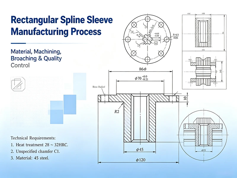
A relief groove at the base of the tooth region mitigates both problems: it gives the cutting tool a clearance zone to complete its stroke, and it provides a chip exit path. The tradeoff is structural — the groove removes material at a cross-section that carries reaction torque from the ring gear, reducing local wall thickness in an already mass-optimized housing. The groove geometry must be sized to serve its machining function without compromising housing stiffness beyond what the structural analysis permits.
Blind-bore configurations add further difficulty
chips cannot fall through, re-cutting risk increases, and forced chip evacuation via coolant pressure becomes necessary. Where housing geometry permits, a through-bore arrangement with a separate closure plate is preferable from a machining standpoint.
Design Considerations Before Manufacturing Begins
Choosing Between Fully Integrated vs Insert-Style Ring Gear
The decision between machining ring gear teeth directly into the housing bore versus pressing in a separate steel ring gear affects tooling, cost, repairability, and achievable accuracy. Neither approach is universally superior.
| Dimension | Fully Integrated | Insert-Style |
|---|---|---|
| Material flexibility | Limited to housing material | Steel insert in aluminum housing |
| Tooth accuracy ceiling | GB class 5–6 (with hard skiving/grinding) | GB class 5 (insert machined independently) |
| Axial length | Minimum | Adds insert wall thickness |
| Repairability | Housing must be replaced if teeth wear | Insert replaceable independently |
| Unit cost at low volume | Lower (fewer parts) | Higher (two components, fit control) |
| Unit cost at high volume | Depends on scrap rate | More predictable — insert is separable |
| CTE mismatch risk | None | Must be designed into fit specification |
The fully integrated approach suits low-to-medium load joints where aluminum is acceptable at the tooth surface, or where a steel housing is used throughout. The insert approach is the practical solution for aluminum housings in load-bearing joints — it recovers tooth durability without abandoning the mass advantage of an aluminum structure.
Module, Tooth Count, and Gear Ratio (Constraints Specific to This Architecture)
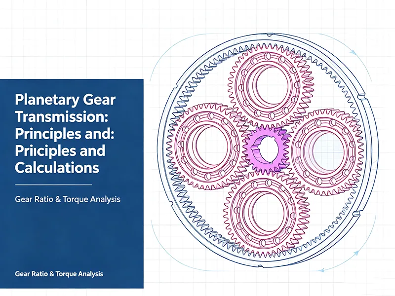
In a planetary stage, the gear ratio is determined by the tooth counts of the sun gear and ring gear. With the ring gear fixed, the ratio is:
i = 1+(z_ring / z_sun)
The ring gear tooth count is constrained by the housing bore diameter and the selected module. For a given bore diameter d(which represents the gear’s inside tip diameter) and module m, the maximum ring gear tooth count is z=(d/m)+2(for internal gears, the pitch diameter equals the bore diameter plus twice the addendum, or d_p=d+2m). Increasing the module to improve tooth strength directly reduces the available tooth count and therefore limits the achievable ratio within a fixed housing diameter.
The axial face width of the ring gear controls tooth load capacity. In a joint module where axial length is tightly budgeted, there is a direct conflict between face width (strength) and the space needed for motor length, bearing spans, and encoder placement. These parameters must be resolved together, not sequentially.
For small-module gears(module ≤1.0) in housings below 60 mm bore diameter, tooth count constraints can make it difficult to achieve ratios above approximately 6:1 in a single planetary stage without resorting to a two-stage configuration or an alternative transmission type. This is because maintaining a 6:1 ratio requires the sun gear to have very few teeth (typically z_sun≤12), which triggers severe undercutting, degrades torque capacity, and leaves insufficient root-circle diameter to accommodate a hollow motor shaft.
Surface Finish and Sealing Requirements
Tooth surface finish. For precision robotic joints, ring gear tooth flank roughness is typically targeted at Ra 0.4–0.8 µm. Finer surface finish reduces running-in wear, lowers friction in the mesh, and supports backdrivability in joints that require it. Power skiving in a well-maintained machine can achieve Ra 0.8 µm or better directly from the cutting operation; reaching Ra 0.4 µm consistently typically requires a subsequent honing or grinding pass.
Lubrication and dynamic sealing. Humanoid joint modules operating under high-speed, high-cycle conditions are commonly lubricated with semi-fluid grease — NLGI grade 00 or 000 — rather than standard grease or oil bath. These grades have low yield stress and flow readily under dynamic conditions, which reduces churning losses and ensures lubricant reaches the tooth contact zone.
O-ring groove placement. The O-ring grooves that seal the housing assembly are typically located on the end faces or outer diameter of the housing. When ring gear teeth are machined into the bore, the tooth region extends axially toward these sealing surfaces. If the tooth runout and the O-ring groove overlap axially, one of two problems occurs: the groove intrudes into the tooth relief zone and weakens the housing wall at that cross-section, or the tooth undercut extends into the sealing surface and compromises groove geometry. Both conditions are avoidable, but only if sealing surface positions are fixed before the gear geometry is finalized — not after.
Quality Control and Inspection for Integrated Ring Gear Motor Housing
Key Inspection Dimensions and Tolerance Classes
For precision robotic joints, integrated ring gear teeth are typically specified at ISO/DIN class 6. Class 5 is reserved for the highest-accuracy requirements and carries a significant cost premium in both machining and inspection.
Three gear deviations govern functional performance:
- Fα (total profile deviation): Controls tooth flank form in the transverse plane.
- Fβ (total helix deviation): Controls how evenly load is distributed across the face width.
- Fp (total cumulative pitch deviation): Controls the angular spacing of all teeth around the pitch cylinder.
Measurement of these parameters in an internal ring gear requires a gear measuring center (GMC) with a stylus small enough to enter the bore and traverse the full tooth profile without interference. CMM alone is insufficient for gear deviation measurement; it is used in conjunction with the GMC for housing-level geometric tolerances — bearing seat cylindricity, stator bore diameter, and concentricity between these features and the ring gear pitch cylinder.
| Inspection item | Method | Typical tolerance (class 6, m=1, d=60mm) |
|---|---|---|
| Total profile deviation Fα | Gear measuring center | ≤ 9 µm |
| Total helix deviation Fβ | Gear measuring center | ≤ 11 µm |
| Cumulative pitch deviation Fp | Gear measuring center | ≤ 22 µm |
| Bearing seat cylindricity | CMM | ≤ 0.005 mm |
| Stator bore / ring gear pitch cylinder concentricity | CMM | ≤ 0.005 mm |
| Tooth flank roughness Ra | Surface profilometer | 0.4–0.8 µm |
Note: Tolerance values are indicative for the stated conditions. Actual values must be derived from the gear standard for the specified module, pitch diameter, and accuracy class.
Functional Inspection Checklist — Integrated Ring Gear Motor Housing
| # | Test item | Method | Accept criterion |
|---|---|---|---|
| 1 | Tooth profile & pitch deviations (Fα, Fβ, Fp) | Gear measuring center | Per specified ISO/DIN class |
| 2 | Concentricity: bearing seat / ring gear pitch cylinder | CMM | ≤ 0.005 mm |
| 3 | Tooth flank roughness Ra | Surface profilometer | 0.4–0.8 µm |
| 4 | Backlash at output | Encoder + locked output fixture | 1–3 arc-min (project-specific) |
| 5 | Pressure decay (sealing) | Dry air, pressure decay method | No measurable decay over hold period |
| 6 | No-load input torque | Torque meter, low-speed drive | Within specified threshold |
| 7 | Backdriving torque | Output-applied torque measurement | Recorded; within specified range |
| 8 | Mesh contact pattern | Gear marking compound | Centered, uniform circumferential distribution |
Sourcing Integrated Ring Gear Motor Housings — What to Look for in a Manufacturer
Manufacturing Capabilities That Actually Matter
An integrated ring gear motor housing is not a standard turned part with a gear feature added. The supplier needs to hold gear accuracy, structural tolerances, and surface finish requirements simultaneously on a single component. The capability gaps between suppliers are significant.
The minimum relevant equipment set:
- Internal gear cutting: Gear shaping machine or, preferably, a power skiving machine with EGB synchronization capability.
- Multi-axis machining center: 4- or 5-axis capability for completing bearing seats, stator bores, and sealing surfaces in minimum setups.
- Gear measuring center (GMC): Required for measuring Fα, Fβ, and Fp on internal gears. A CMM alone does not substitute.
- Heat treatment and post-hardening finishing: If steel housings or steel inserts are involved, the supplier must either operate heat treatment in-house or have a verified closed-loop with an external facility, followed by hard skiving or internal grinding capability to correct distortion.
Why Custom Integrated Ring Gear Housings Require Early DFM Collaboration
Integrated ring gear housings have enough geometric interdependencies — between gear tooth position, sealing grooves, bearing fits, undercut zones, and structural wall thickness — that design changes after drawing freeze are consistently more expensive than changes made during design development.
Common DFM issues that surface late when the supplier is not involved early:
- Relief groove depth conflicts with housing wall thickness at the gear root
- O-ring groove placement overlaps with tooth runout zone
- Bore depth-to-diameter ratio exceeds what the specified gear cutting process can reach without accuracy penalty
- Specified accuracy class requires post-hardening grinding, but bore geometry does not admit a grinding wheel of sufficient diameter
Information required before a meaningful quote can be issued:
| Parameter | Details needed |
|---|---|
| Gear geometry | Module, tooth count, pressure angle, helix angle (if helical) |
| Accuracy class | ISO/DIN/GB class; which deviations are drawing-controlled |
| Housing material | Alloy specification; heat treatment requirement |
| Ring gear type | Fully integrated or insert-style; if insert, fit class |
| Critical tolerances | Concentricity, cylindricity, surface finish requirements |
| Annual volume | Prototype quantity; projected production volume |
| Required lead time | First article; production delivery |
Submitting a complete drawing without this information available for discussion is workable. Submitting an incomplete drawing and expecting a firm quote and delivery commitment is not.
FAQ
In a standard planetary gearbox, the ring gear is a discrete component. An integrated ring gear motor housing eliminates that separate component: the internal gear teeth are machined directly into the motor housing bore.
It depends on the contact stress at the tooth surface. 7075-T6 aluminum has a post-aging hardness of approximately 87 HRB, adequate for low-load joints such as wrist rotation or head movement, where calculated contact stresses remain within the material's fatigue limit. For load-bearing joints in the lower limbs, aluminum tooth flanks will wear under sustained operational loads.
Most precision humanoid joint applications specify ISO/DIN class 6 for the ring gear. Class 5 is used where transmission error requirements are most stringent; class 7 is the lower practical boundary for joints with positional repeatability specifications. Power skiving is currently the most capable process for achieving class 5–6 on internal ring gears in motor housing bores, combining the bore-access capability of gear shaping with cutting speeds and accuracy levels that reciprocating shaping cannot match. Reaching class 5 consistently typically requires hard skiving or internal gear grinding after heat treatment.