Worm Gear Machining Process A Step-by-Step Guide to Pre- and Post-Heat Treatment Operations
Blog 2026-08-27
Worm gear machining is never a simple sequence of cutting operations. The interplay of machining order, datum selection, heat treatment, and final finishing determines whether the finished part holds its required geometry. Machine accuracy and tool quality matter, but they do not compensate for a flawed process sequence.
We structure the entire process logic as follows:
Rough machining establishes the basic shaft geometry. Datum and assembly surfaces provide the locating references for subsequent operations. Spiral machining must be planned around the heat-treatment stage. Heat treatment delivers the required hardness and material properties, but it simultaneously alters dimensions and geometry. Post-treatment re-machining corrects these changes. Final precision machining and finishing restore the specified dimensions and surface quality.
A complete worm machining process comprises six stages:
Rough Machining → Datum / Assembly Surface Preparation → Pre-Heat-Treatment Spiral Machining → Heat Treatment → Post-Heat-Treatment Re-Machining → Final Precision Machining & Finishing
This sequence is mandatory. Any deviation in the order or allowance strategy at any stage cannot be remedied later. In the following chapters, we break down the execution details and decision criteria for each step.
What Determines the Worm Gear Machining Process?
Not every worm shaft follows the same machining sequence. Two parts with identical drawings and materials can require entirely different process routes, depending on a single decision.
The Most Important Process Decision: Will the Spiral Surface Be Machined After Heat Treatment?
That decision determines the allowance strategy, the selection of pre-treatment processes, and whether the final geometry can actually be achieved.
We face two distinct cases.
Case 1 — Post-Heat-Treatment Grinding Is Required
When the design calls for grinding the worm spiral after hardening, the process route must reserve grinding allowance before heat treatment. The sequence runs:
Pre-treatment rough and finish machining → leave a defined grinding stock → heat treatment → post-treatment grinding of the spiral surface.
Grinding after heat treatment removes the decarburized layer, corrects thermal distortion, and restores the intended profile and lead accuracy. Without that pre-left stock, the grinding wheel has no material to engage. The part is scrap.
Case 2 — No Post-Heat-Treatment Machining
When the spiral surface will not be machined again after hardening, the entire burden shifts to the pre-treatment stage. The sequence runs:
Pre-treatment finish machining to final contour → predict heat-treatment deformation → compensate the tool path or dimensions for the expected change.
In this route, there is no second chance to correct form error or lead deviation. The pre-treatment finish operation must account for the predictable effects of quenching (dimensional growth, shrinkage, or distortion) and build the inverse compensation into the cutting pass.
Decide the allowance strategy during process planning, not add it later. The branch decision belongs at the front end, before the first chip is removed.
Step 1 — Rough Machine the Worm Shaft
Rough machining removes the bulk stock from the forged or bar-stock blank and establishes the fundamental shaft geometry: straightness, concentricity, and basic diameters. This step prepares the workpiece for datum preparation and subsequent spiral cutting.
We start by machining all external cylindrical surfaces, end faces, and shaft shoulders where the design requires them. We do not cut the worm thread or spiral at this stage. That operation waits until the assembly surfaces and locating datums are finished, because the spiral must reference those datums for positional accuracy. Roughing the thread too early risks losing the lead-to-datum relationship once the datums are later corrected.
Stock removal must leave sufficient material for all downstream operations, including semi-finishing, datum finishing, and post-heat-treatment grinding when required by the process route. The roughing pass should generate a uniform envelope around the finished geometry, with consistent stock distribution for subsequent setups.
We drill center holes before rough turning to provide a rotational axis for the initial cuts. The final datum center holes are machined in Step 2. The key is to avoid inducing excessive runout or taper that cannot be cleaned up later. Ensure the rough-turned shaft remains within a reasonable envelope of straightness and concentricity before handing it off to datum preparation.
Step 2 — Finish the Assembly Surfaces and Machining Datums
We do not cut the worm spiral immediately after roughing. The assembly surfaces and locating datums come first, because the spiral must be generated relative to a stable, finished reference system.
Why Datum Preparation Matters Before Spiral Machining
The assembly surfaces (bearing journals, shoulders, mounting faces) and locating surfaces establish the dimensional relationship between the shaft’s functional interfaces and the worm spiral. If we machine the spiral before these surfaces are finished, we have no reliable reference to control its axial position, lead, or runout relative to the bearing centers.
A finished datum system does more than locate the part for a single operation. It allows subsequent operations and inspection to use a consistent rotational reference from spiral cutting to post-treatment re-machining to final quality checks. That consistency prevents geometric errors from accumulating through the process chain.
When the Worm Does Not Require Heat Treatment
For worms that do not undergo hardening, we machine the assembly surfaces and datum surfaces directly to final dimensions in this step. No allowance is carried forward. Once finished, these surfaces serve as the permanent reference for all remaining operations, including spiral cutting and final inspection.
When Heat Treatment Is Required
For worms that will be hardened, these surfaces must retain the allowance required for post-treatment correction.
| Condition | Assembly / Datum Surface Strategy |
|---|---|
| No heat treatment | Finish to final size in Step 2 |
| Heat treatment required | Reserve allowance; re-machine after hardening |
For hardened worms, final datum correction must be completed after the thermal cycle. The same process-planning principle applies to the spiral.
Step 3 — Machine the Worm Spiral Surface Before Heat Treatment
At this stage, we cut the worm thread or spiral on the shaft. The critical question is not how to cut it, but to what condition, because that determines whether the part survives heat treatment and still meets the final geometry.
Rough and Finish the Spiral Surface Before Heat Treatment
We perform both rough machining and finish machining of the spiral before the part enters the furnace. Roughing removes the bulk of the thread stock. Finishing brings the spiral to a controlled state, either to final dimensions or to a pre-defined allowance condition, depending on the downstream route.
The pre-treatment spiral operation does more than shape the thread. It prepares the spiral surface for whatever follows, whether that is grinding after hardening or no further cutting at all. The process planning for this step must be locked before the first spiral pass is programmed.
When Post-Heat-Treatment Grinding Is Required
If the process route specifies grinding the spiral after heat treatment, we must leave sufficient grinding allowance during pre-treatment spiral machining.
The process route is:
Pre-treatment spiral machining → leave grinding stock → heat treatment → post-treatment grinding.
When the Spiral Will Not Be Machined Again
When the design does not call for post-treatment spiral machining (no grinding, no hard turning), the pre-treatment finish operation becomes the final shaping pass. In this case, we must predict the heat-treatment deformation and compensate the tool path or dimensions accordingly.
After hardening, there is no further opportunity to correct lead error, profile deviation, or runout. The pre-treatment spiral finish must therefore account for the expected dimensional changes introduced by the heat-treatment cycle. This requires empirical data or validated simulation for the specific material, geometry, and quench process.
These two branches (grinding after heat treatment versus no post-treatment machining) are the single most important process decision in worm gear machining.
Step 4 — Heat Treatment and Its Effect on Worm Geometry
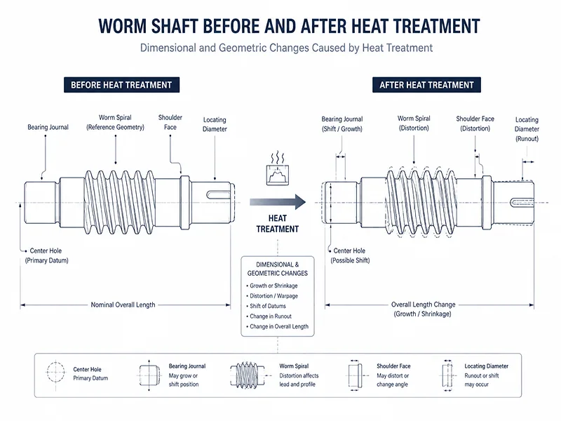
Heat treatment delivers the required hardness and material properties, but it also changes dimensions and geometry. That is the trade-off we manage.
The furnace cycle transforms the microstructure to achieve the specified surface hardness and core strength. For worm shafts, this often means quenching and tempering, carburizing, or nitriding, depending on the material and load requirements. The thermal cycle introduces volume changes from phase transformation, stress relief, and sometimes distortion from uneven heating or cooling.
These changes are not random. We can predict them within a range for a given material, section size, and quench method. But predictable does not mean negligible. A shaft can grow in diameter, bow along its length, or shift in lead over the worm length. The mounting surfaces and locating diameters also shift, losing their pre-treatment positional accuracy.
Because heat treatment alters both the part’s dimensions and its geometric relationships, the machining route must anticipate these changes. The process planner does not treat heat treatment as an isolated operation. It dictates how we prepare the part before the furnace and what we re-machine afterward.
Why Heat Treatment Allowance Must Be Planned in Advance
Allowance is part of process planning, not an extra dimension added after machining. We determine the required stock on each surface before the part enters heat treatment. Grinding allowance on the spiral, extra material on bearing journals, and stock on locating faces are all engineered into the pre-treatment geometry.
Allowance cannot be added after machining. Once a surface has been cut to final dimensions, no material remains for post-treatment correction. The planner must specify the pre-treatment dimensions (finished contour minus stock) and ensure the cutting tools generate that geometry. The heat-treatment cycle then transforms the part, and post-treatment re-machining removes the stock to restore the final print dimensions.
Step 5 — Re-Machine the Mounting and Locating Surfaces After Heat Treatment
After heat treatment, we do not move directly to final spiral grinding or finishing. The mounting surfaces and locating surfaces come first.
Heat treatment can alter these surfaces. Bearing journals may shift, shoulder faces may distort, and locating diameters may no longer run true to the shaft axis. Using these surfaces without correction would give subsequent operations an inaccurate datum.
We re-machine these surfaces after heat treatment to restore their dimensions and positional relationships before final precision machining.
Why Post-Heat-Treatment Datum Correction Matters
Consider what happens if we skip this step. The mounting surfaces and locating diameters have moved during the thermal cycle. If we clamp the part using these surfaces and proceed to grind the spiral or finish the journals, we cut the new features relative to a shifted reference.
The result: the final geometry does not match the intended relationship between the spiral and the mounting surfaces. The spiral may run out relative to the bearing journals. The lead may be correct relative to the center holes but incorrect relative to the assembly faces. The part fails to function in its assembly because the datum system used for final machining does not align with the datum system that the end customer will use for installation.
Correcting the mounting and locating surfaces after heat treatment re-establishes a stable, accurate datum system. We machine these surfaces to their final print dimensions and, crucially, to the same axis that the spiral will reference. This ensures that subsequent operations, whether grinding the spiral or finishing other features, use a datum system consistent with the part’s assembly and inspection requirements.
We machine these surfaces after heat treatment using the same center holes that served as pre-treatment datums, provided those center holes remain serviceable. In some cases, we rework or re-grind the center holes themselves before re-machining the mounting surfaces to ensure the rotational reference is restored. Once the locating surfaces are corrected, we can proceed to final precision work with confidence that the datum chain is intact.
Step 6 — Final Precision Machining and Finishing
Final precision machining and finishing serve one purpose: bring the worm to the required geometry and achieve the specified final surface condition.
At this stage, all previous operations (roughing, datum preparation, pre-treatment spiral cutting, heat treatment, and post-treatment re-machining) converge. The part has a corrected datum system and sufficient stock left on the critical surfaces. Final machining removes that stock and establishes the final dimensions, form, and surface finish.
The specific method depends on the material condition and required accuracy. For hardened worms, grinding is the standard final operation. For unhardened worms, hard turning or finish turning may suffice. In either case, the final pass must produce the contour, lead accuracy, flank finish, and runout tolerances called out on the print without compromising the datum relationships established in Step 5.
When Final Grinding Is Used
For worms that require post-heat-treatment grinding, final grinding closes the process loop:
Grinding allowance intentionally left before heat treatment → final grinding removes that allowance → dimensional and geometric corrections completed after heat treatment.
The grinding wheel corrects any distortion introduced by the thermal cycle, removes the decarburized layer, and generates the final flank profile and lead accuracy. Because grinding allowance was left during pre-treatment spiral machining, the final grinding operation has sufficient stock to complete the required correction.
The final grind also ensures that the spiral surface runs true to the corrected datum system. We grind the worm using the same center holes or corrected locating surfaces that we re-machined in Step 5, maintaining a consistent rotational reference throughout the entire process chain. Once the final grind is complete, the part meets both dimensional and surface requirements and is ready for inspection and assembly.
How Heat Treatment Changes the Worm Machining Strategy
Heat treatment changes not just the part but the entire machining strategy. The presence or absence of post-treatment spiral work dictates the allowance plan, the cutting conditions used before hardening, and the inspection criteria applied at each stage.
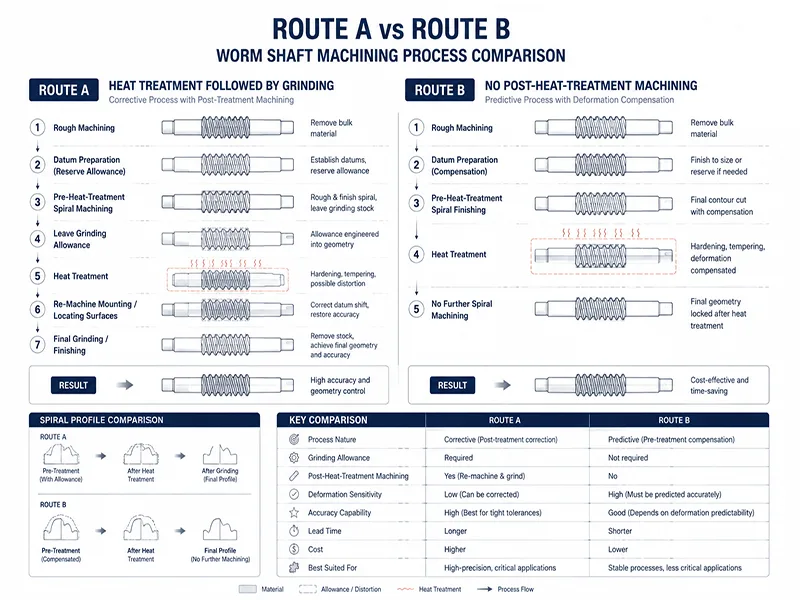
We run two distinct process routes in production. Understanding which one applies to a given part is the difference between a predictable process and one that produces intermittent scrap.
Process Route A — Heat Treatment Followed by Grinding
Route A applies when the spiral surface will receive post-treatment machining, typically grinding.
This route is generally preferred for high-hardness worms, tight-tolerance applications, or parts where the hardening response is not fully characterized. Post-treatment grinding provides the corrective operation needed to restore the required geometry after hardening.
Process Route B — No Post-Heat-Treatment Machining
Route B applies when the spiral surface will not be machined again after heat treatment.
In this route, the pre-treatment finish operation must compensate for expected heat-treatment deformation. We adjust the tool path or dimensions during the finishing pass to account for predicted growth, shrinkage, or distortion. The part comes out of the furnace at final geometry, assuming the compensation model is accurate.
This route eliminates post-treatment grinding but carries higher process risk. If the deformation prediction is inaccurate, the final spiral geometry cannot be corrected after hardening.
How to Choose Between the Two Routes
The choice hinges on three practical questions:
| Question | Yes | No |
|---|---|---|
| Will the spiral be ground after heat treatment? | Leave grinding allowance; use Route A | Continue with deformation compensation; use Route B |
| Can the mounting surfaces shift during heat treatment? | Plan post-treatment re-machining (Route A or partial Route B with datum correction) | Verify dimensional stability; proceed without re-work |
| Is final geometry highly critical? | Favor a corrective post-treatment route (Route A) | Pre-treatment compensation may be sufficient |
The third question is engineering judgment. For high-lead-accuracy worms, ground aerospace components, or parts mated to precision worm wheels, Route A is typically the safer path. For lower-precision applications, stable materials, or well-characterized processes, Route B can reduce cost and cycle time. The process planner evaluates the specific requirements (print tolerances, production volume, heat-treatment capability, and inspection method) and selects the route that matches the risk profile.
Route B is not inferior. It is simply different. The key is making the choice at the planning stage, not discovering mid-way that the pre-treatment finish does not match the post-treatment reality.
Machining Datums for Worm Shafts and Worm Wheels
The datum system determines whether the process chain holds geometry or propagates error. We select datums that serve double duty: locating the part during machining and providing the same reference for inspection.
Worm Shaft Datum — Center Holes at Both Ends
We use center holes at both ends of the worm shaft as the primary machining and inspection datum. These holes establish the rotational reference axis for the entire part.
The center holes support the shaft between centers during turning, grinding, and inspection where the equipment permits. The axis defined by the center holes is the same axis used to generate the worm spiral, machine the bearing journals, and check runout and lead accuracy.
We machine the center holes early, typically during datum preparation in Step 2, and maintain them throughout the process chain. If the center holes become damaged during handling or heat treatment, we rework them before any precision operation. The axis they define is the axis that matters.
Worm Wheel Datum — Bore and End Face
For worm wheels, the datum system differs. We use the bore and one end face as the machining and inspection datums.
The bore establishes the rotational axis. The end face provides the axial locating surface. Together, they define the wheel’s orientation relative to the worm shaft and the housing. All cutting operations (hobbing, shaving, or finishing) reference this bore-and-face combination. Inspection checks the wheel geometry, runout, and tooth contact relative to these same surfaces.
We maintain consistency between the machining setup and the assembly condition. The bore and face used during cutting must match the bore and face used during final installation. Any deviation introduces alignment error that cannot be corrected downstream.
Why Repeated Datum Changes Can Increase Runout
The process chain performs best when every operation uses the same datum system. Changing datums between operations introduces geometric error from one setup to the next.
Consider a worm shaft machined between center holes for spiral cutting, then transferred to a chuck for bearing journal grinding using the journals themselves as a locating surface. The chuck references the OD. The center holes reference the axis. If the OD has runout relative to the center holes, even a few microns, the grinding operation will cut the journals to a different axis than the spiral. The result is runout between the journals and the spiral.
Runout is not a single-point error. It accumulates. Each datum change adds its own contribution: chuck clamping distortion, concentricity error between the new locating surface and the previous axis, or axial shift from face locating. By the time the part reaches final inspection, the total runout can exceed the tolerance even though each individual setup was within its own specification.
We therefore minimize datum changes. We keep the part on its primary datum system (center holes for shafts, bore and face for wheels) for as many operations as possible. When a change is unavoidable, we qualify the new datum against the old one and account for any offset in the machining program. Parts with tight runout requirements are almost always the ones where the datum chain remains unchanged from rough machining through final grinding. The moment a setup shifts to a different locating surface without requalification, the runout number moves.
Common Worm Gear Machining Problems Caused by Incorrect Process Routing
When the process route is wrong, the problems show up on the inspection bench, not in the planning documents. Below are the most common failures we see from incorrect routing decisions.
Excessive Runout
Runout traces back to the datum system. If we change locating references between operations or fail to correct post-treatment datum shift, the spiral and the mounting surfaces no longer share a common axis.
The root causes are straightforward: inconsistent machining references, incorrect locating surface selection, or clamping the part on a surface that does not align with the primary datum. Each setup introduces its own centering error. By the time the part reaches final inspection, the accumulated runout exceeds the tolerance, and the part fails to assemble or run quietly.
We see this most often when the worm spiral is cut using center holes, but subsequent journal grinding uses the OD as a chucking reference without requalifying the relationship between the two.
Dimensional Shift After Heat Treatment
Heat treatment changes dimensions. The problem occurs when the process route does not account for it, either by leaving insufficient allowance or by failing to re-machine critical surfaces after hardening.
Without post-treatment correction, mounting surfaces, locating diameters, and overall shaft length can shift out of tolerance. The part may grow, shrink, or bow, depending on the heat-treatment response. Pre-treatment dimensions must therefore account for the expected thermal changes.
This failure is a planning error, not a shop-floor execution error.
Spiral Surface Cannot Be Corrected After Heat Treatment
This is one of the most serious process failures. When the spiral receives no post-treatment machining and the deformation prediction is inaccurate, the final spiral geometry cannot be corrected after hardening.
The root cause is either insufficient allowance for post-treatment correction or reliance on an unvalidated deformation model.
Final Geometry Does Not Match the Intended Datum Relationship
The final part may pass individual feature checks yet fail assembly. This happens when the datum chain is broken. The spiral was cut referencing one datum system. The mounting surfaces were finished referencing another. Final inspection used yet a third reference.
The result: the spiral lead or profile is correct relative to its own cutting axis, but that axis does not align with the bearing journals or assembly faces. The part measures fine on the gear checker, but it does not fit the housing or mate correctly with the worm wheel.
This problem is preventable. Maintain a single, consistent datum system through the entire process chain, from rough machining to final inspection. Correct post-treatment surfaces before any precision finishing. Verify that the inspection setup uses the same datums as the machining setup.
Worm Gear Machining Process Checklist Before Production
Before we release a job to the shop floor, we run through a checklist. Not to catch errors, but to prevent them. Below is the set of items we review for every worm gear order.
Drawing Review
We start with the print. The drawing defines what we are making and what matters most. We verify:
- Worm profile — ZA (axial straight-sided) or ZN (normal straight-sided)? The profile determines the cutting tool geometry and the inspection method.
- Dimensions — Overall shaft length, mounting diameters, journal positions, and thread length. We check for completeness and consistency across views.
- Machining surfaces — Which surfaces are functional and require final finishing? Which are non-functional and can remain as-machined?
- Locating datums — Are the center holes called out as primary datums? Does the drawing specify which surfaces control axial and radial location?
- Heat treatment requirements — Hardness range, case depth, and any restrictions on post-treatment straightening or grinding.
- Final finishing requirements — Surface finish (Ra or Rz), lead accuracy, profile tolerance, and runout specifications.
We flag missing datums, ambiguous notes, or conflicting requirements before quoting, not after machining starts.
Process Planning
Once we understand the drawing, we define the sequence. The process plan must cover every operation from raw material to finished part:
- Rough machining sequence — Which surfaces get roughed first? How much stock remains for subsequent operations?
- Datum preparation — When are center holes machined? What surfaces get finished to size before spiral cutting?
- Spiral machining — Is the spiral roughed and finished before heat treatment, or only roughed with a finish pass after hardening?
- Heat treatment — What cycle? At what stage in the sequence does it occur?
- Post-treatment correction — Which surfaces require re-machining after hardening? What is the re-machining sequence?
- Final finishing — What method (grinding, hard turning, lapping) generates the final spiral and mounting surfaces?
The process plan must be complete before we write a single CNC program.
Allowance Planning
Allowance is the most commonly overlooked item in process planning. We confirm:
- Is heat treatment required? — If no, finish surfaces to print dimensions during pre-treatment stages. If yes, reserve stock on all surfaces that shift during the thermal cycle.
- Will spiral grinding follow heat treatment? — If yes, leave grinding allowance on the spiral flanks and root diameter. If no, plan for deformation compensation during pre-treatment finishing.
- Is enough allowance reserved? — Confirm that the planned stock is sufficient for post-treatment correction without requiring excessive material removall.
- Is deformation compensation required? — For Route B (no post-treatment spiral machining), we confirm that the tool path or dimensions are offset to account for predicted growth or shrinkage.
Allowance comes from experience with the material, heat-treatment process, and part geometry. We review it for every new part family and update it as we gather production data.
Inspection Reference
Inspection does not happen after machining. It is planned before. We confirm:
- Machining datum — What surfaces are used to locate the part during cutting? Center holes for shafts. Bore and face for wheels.
- Measurement datum — Are the inspection fixtures and gauges referencing the same surfaces as the machining setup? If not, the measured geometry will not match the manufactured geometry.
- Relationship between worm geometry and mounting surfaces — The spiral must be concentric and axially positioned relative to the bearing journals or assembly faces. We verify that the print specifies this relationship and that our process maintains it.
We build the inspection plan at the same time as the process plan. The inspection method and the machining method must reference the same datum system. If they do not, the part will fail inspection even when it is cut correctly, or worse, pass inspection when it does not fit the assembly.
FAQ
The standard process sequence includes six stages: rough machining the shaft, finishing assembly surfaces and machining datums, cutting the spiral before heat treatment (with or without grinding allowance), heat treatment to achieve required hardness, re-machining mounting and locating surfaces after hardening, and final precision machining and finishing to restore geometry and surface condition. This sequence is mandatory for most hardened worm shafts.
Before. We always cut the spiral before the part goes to the furnace. The question is not whether to machine it before heat treatment, but to what condition: final dimensions or with grinding allowance. If the spiral will be ground after hardening, we cut it with stock left on. If it will not be machined again, we finish it to final contour before heat treatment and compensate for expected deformation.
Grinding allowance provides material for post-heat-treatment grinding, allowing the process to correct heat-treatment-induced dimensional changes, distortion, and profile or lead errors.
Center holes establish the rotational reference axis for the entire part. We use the same center holes for turning, grinding, and inspection. This consistency prevents runout accumulation and ensures that the spiral, journals, and mounting surfaces all reference the same axis.
Heat treatment changes dimensions and geometry on mounting surfaces, locating diameters, and shoulders. If we do not re-machine them after hardening, the datum system shifts. Subsequent operations, whether spiral grinding or journal finishing, will cut relative to the shifted reference, producing a part whose mounting surfaces do not align with the spiral. Re-machining these surfaces after heat treatment restores their correct dimensions and positional relationships before any final precision work proceeds.
If you are planning a worm gear production run and need a process review for your specific material and tolerance requirements, contact our engineering team for a routing evaluation.