Mastering Worm Gear Manufacturing: Process Routing, Material Selection, and Heat Treatment Limits
Blog 2026-08-20
Worm gears transmit motion and torque between two shafts that are nonparallel and nonintersecting. Their compact layout, smooth transmission, and relatively high transmission ratios make them useful in applications where space and motion stability matter. Typical reduction ratios range from 5-70, while speed increase ratios range from 5-15.
The main trade-off comes from the sliding contact between the worm and worm wheel. This contact creates higher friction losses than conventional gear pairs and can increase heat generation, temperature rise, and wear. Reliable worm gear manufacturing therefore depends on the complete process route, including profile selection, datum control, heat treatment, material selection, and final finishing.
DFM for Custom Worm Gears: Analyzing Metric Thread Profiles
Before machining custom worm gears, the tooth profile needs to be reviewed from a manufacturing perspective. Worm drives fall into three main groups: cylindrical worm gears, toroidal worm gears, and conical worm gears. A cylindrical worm has a tooth form similar to a trapezoidal thread. Common tooth angles are 40°for metric worms and 29°for inch worms. For metric worms, the 40°
tooth angle corresponds to a 20°pressure angle.
Metric Worm Profiles: ZA vs. ZN
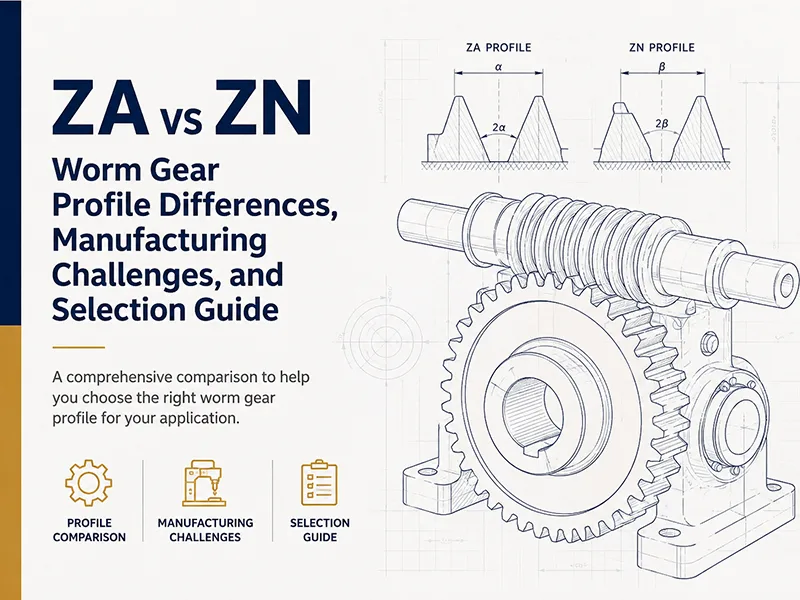
Metric worms use two main profile forms, ZA and ZN. The difference is defined by the section in which the tooth flanks appear as straight lines. That difference also affects the manufacturing route for the worm wheel.
| Worm profile | Profile definition | Profile in the section perpendicular to the worm axis |
|---|---|---|
| ZA — Archimedes worm | Straight lines in the axial section | Archimedes spiral |
| ZN — Extended involute worm | Straight lines in the normal section | Extended involute |
For a ZA worm, both tooth flanks are straight in the axial section. In the section perpendicular to the worm axis, the profile forms an Archimedes spiral. This is why ZA worms are also called Archimedes worms.
For a ZN worm, the tooth flanks are straight in the normal section. In the section perpendicular to the worm axis, the profile forms an extended involute. The corresponding worm wheel is more difficult to manufacture than the wheel used with a ZA worm.
Which Profile Should You Choose for Custom Worm Gears?
For worm gear production, ZA is usually the more practical choice when the design does not specifically require ZN. The source material notes that ZN worm wheels are more difficult to manufacture, which is why most industrial applications use the ZA profile.
This is a useful DFM decision to make during drawing review. If the transmission does not require ZN geometry, choosing ZA can simplify the worm wheel manufacturing route and avoid unnecessary production complexity.
The Complete Worm Gear Machining Process Routing
The machining route for a worm must account for the sequence of rough machining, datum preparation, spiral machining, heat treatment, post treatment machining, and final finishing. The key process decision is whether the worm spiral surface will be machined again after heat treatment.
Six step precision machining workflow
A typical process route follows six stages.
Rough machine the worm shaft surfaces
Remove the bulk of the material and establish the basic shaft geometry.
Finish the assembly surfaces or machining datums
For a worm that does not require heat treatment, these surfaces can be machined directly to the finished dimension. When heat treatment is required, leave the necessary machining allowance.
Rough and finish machine the worm spiral surface
When the spiral surface will be ground after heat treatment, leave sufficient grinding allowance before the heat treatment step. If the spiral will not receive further machining, the pre treatment finish operation must account for the expected heat treatment deformation.
Perform the required heat treatment
Heat treatment provides the required material properties and hardness, but it can also change dimensions and geometry.
Re machine the mounting and locating surfaces after heat treatment
The installation and datum surfaces may need correction after heat treatment before the final precision operations.
Complete final precision machining and finishing
Final machining and finishing bring the worm to the required geometry and surface condition.
How to manage heat treatment allowance on the worm spiral
The required allowance depends on what happens after heat treatment.
When the worm spiral will receive post treatment grinding, the spiral surface must retain enough grinding allowance before heat treatment. The final grinding operation can then correct the dimensional and geometric changes introduced during heat treatment.
When no machining will follow the heat treatment, the process has to account for deformation before the heat treatment takes place. The pre treatment finishing operation must therefore compensate for the expected dimensional change instead of relying on a later correction step.
This distinction should be decided during process planning. The allowance is part of the manufacturing route, not a dimension that can be added independently after the machining sequence has already been fixed.
Which machining datums control worm gear runout?
Consistent datum selection is essential when the goal is to control runout and the relationship between the worm geometry and its mounting surfaces. Repeated datum changes can introduce geometric error from one operation to the next.
For the worm shaft, the usual machining and inspection datum is the center hole at each end of the shaft. These center holes establish the rotational reference axis for machining and measurement, which is particularly important for a slender shaft.
For the worm wheel, the usual machining and inspection datums are the bore and end face. These surfaces provide the reference for subsequent machining and measurement.
When finished parts show persistent runout, review the datum chain before changing the final cutting conditions. A locating error introduced early in the route can remain present through several downstream operations.
Material Selection & Heat Treatment Guide from Top Worm Gears Suppliers
The worm and worm wheel need sufficient strength, wear resistance, and resistance to galling for the intended operating condition. Material selection should therefore match the load, speed, precision requirement, and expected wear condition.
Worm wheel materials for sliding wear resistance
Common worm wheel materials include:
- Cast tin bronze
- Cast aluminum iron bronze
- Gray cast iron
These materials are among the main choices for worm wheels.
When a worm wheel is made from cast iron, aging treatment should be included to reduce the risk of deformation.
Worm Shaft Material & Hardness Matrix
The material and heat treatment of the worm shaft should match the operating condition. The following matrix summarizes the material, heat treatment, and hardness recommendations in the source material.
| Operating condition | Recommended worm shaft material | Heat treatment | Target hardness |
|---|---|---|---|
| Low speed, medium load, non-critical duty | 40 steel or 45 steel | Quenching and tempering | 220–250 HBW |
| Speed < 2 m/s, precision thread grinding required | 45 steel | Quenching and tempering | 45–50 HRC |
| High speed, light load, small/medium size | 15 steel | Carburizing, quenching, and low-temperature tempering | 56–62 HRC |
| High wear resistance / high hardness | 40Cr, 42SiMn, or 45MnB | Oil quenching and tempering | 45–50 HRC |
| Medium load, high precision, bronze worm wheel | 35CrMo | Quenching and tempering | 255–303 HBW |
| Very high hardness, minimum deformation | 38CrMoAlA or 38CrAlA | Normalizing or quenching and tempering, followed by nitriding | >850 HV |
For the 35CrMo condition, the specified heat treatment uses 850-870°C oil quenching followed by 600-650°C tempering, with a target hardness of 255-303 HBW.
For applications requiring very high hardness with minimum deformation, 38CrMoAlA or 38CrAlA can be normalized or quenched and tempered before nitriding. The specified hardness is >850 HV.
The other material combinations in the matrix follow the same principle: the selected steel and heat treatment must match the operating condition rather than being chosen independently of speed, load, and machining requirements.
Conclusion
Reliable worm gear manufacturing starts with the correct profile and continues through every stage of the process route. For metric worms, ZA and ZN should be evaluated from a DFM perspective. The machining sequence must account for heat treatment allowance, and the final process should maintain consistent machining datums. Material selection and heat treatment must then match the required load, speed, wear resistance, hardness, and dimensional stability.
Hansheng Automation applies these process and material requirements when reviewing and manufacturing custom worm gears. If you are looking for a worm gear manufacturer or reliable worm gears suppliers, send us your drawing and application requirements. Our engineering team can review the design from a DFM perspective and provide a detailed quotation with manufacturing recommendations within 24 hours.
FAQ
Metric worms use a 40° tooth angle, corresponding to a 20° pressure angle, and include ZA and ZN profile forms. The worm wheel for a ZN worm is more difficult to manufacture, so most industrial applications use the ZA profile.
For custom worm gears, ZA is therefore the more practical choice when the transmission does not require ZN geometry.
A cast iron worm wheel should generally receive aging treatment to reduce the risk of deformation.
The process depends on whether the spiral surface will be machined after heat treatment. If post treatment grinding is required, leave grinding allowance before heat treatment. If no machining will follow, account for the expected heat treatment deformation during the pre treatment finishing stage.
For the worm shaft, the usual machining and inspection datum is the pair of center holes at both ends. For the worm wheel, the usual datums are the bore and end face.
The source recommends 38CrMoAlA or 38CrAlA, followed by nitriding after normalizing or quenching and tempering. The specified hardness is >850 HV.