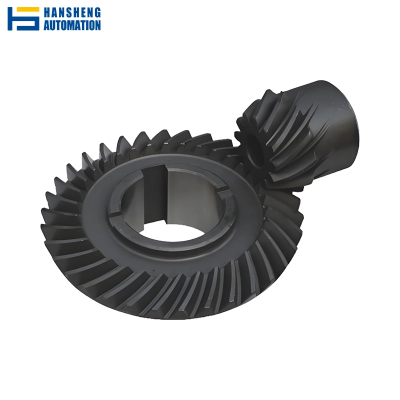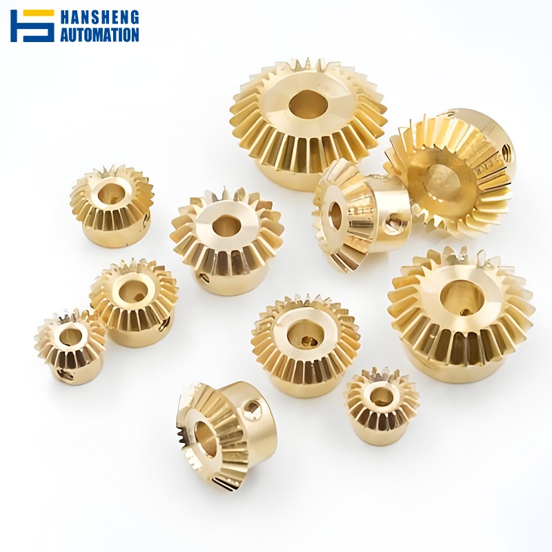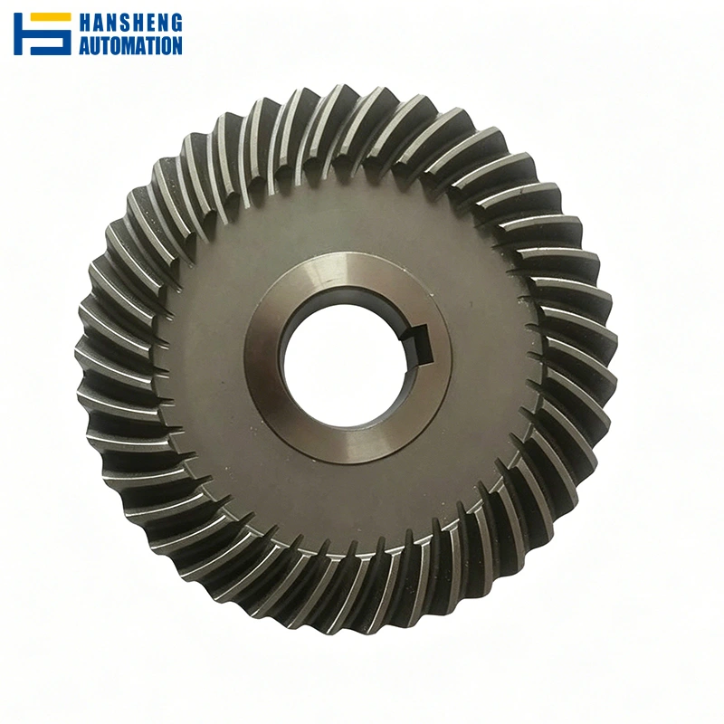

Hypoid Bevel Gear
Type: Hypoid Bevel Gear (offset-axis)
Precision: Up to ISO/DIN/GB Grade 6
Module: 0.5 – 5.0 mm
Diameter: 3 – 300 mm
Custom: Shaft integration, offset, contact pattern, material & heat treatment per drawing
Introduction
As an experienced manufacturer of custom precision gears, Hansheng Automation provides high-precision Hypoid Bevel Gears manufactured strictly in accordance with client-provided engineering drawings. We fully support low-minimum-order-quantity (low MOQ) production for prototyping and small-batch customization, backed by streamlined manufacturing processes to ensure rapid and predictable lead times.
Manufacturing Capabilities & Specifications
Below are the verified technical boundaries and equipment capabilities of Hansheng Automation for custom-to-drawing Hypoid Bevel Gear production.
| Module Range | 0.5 – 5.0 (standard and non-standard DP) |
| Diameter Range | 3.0 mm – 300.0 mm |
| Accuracy Grade | Up to ISO/DIN/GB 6 (achieved via CNC gear grinding) |
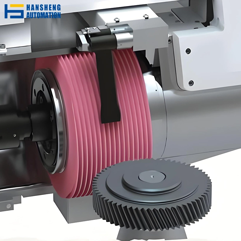
| Tooth Cutting Process | Face Milling or Face Hobbing (CNC hypoid gear cutting machines) |
| Tooth Finishing Process | CNC Profile Grinding (Ra 0.4 μm) |
| Gear Ratio (single stage) | 1:1 up to 10:1 |
| Offset Distance | Customized per drawing (recommended ≤25% of crown gear pitch diameter) |
| Surface Roughness | Down to Ra 0.4 μm (ground) |
Advanced Machinery
- Hypoid Gear Cutting – Dedicated multi‑axis CNC milling/hobbing machines (e.g., Gleason/Klingelnberg type) for roughing and semi‑finishing.
- Precision Grinding – CNC gear grinding equipment for finishing hardened teeth to DIN 5 or better.
- Supporting Processes – For other gear types, we also offer skiving and hobbing services, but hypoid gears are exclusively produced using specialized cutters and machines to ensure correct tooth flank geometry.
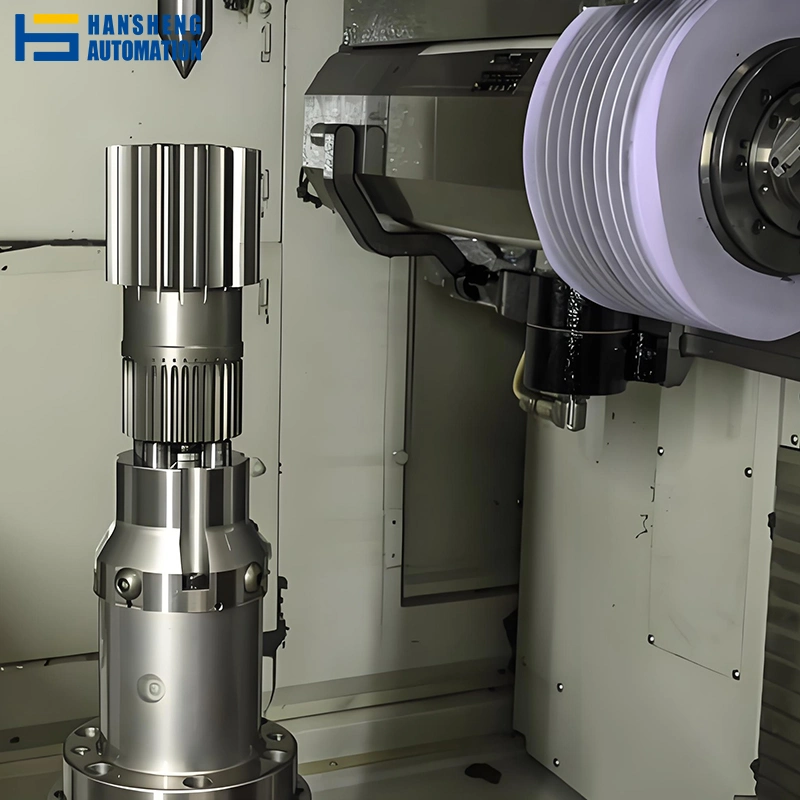
Material & Heat Treatment Options For Hypoid Bevel Gear
Material Options
Alloy Steels (For Heavy-Duty and High-Impact Loads)
Common Grades: 20CrMnTi, 18CrNiMo7-6, SAE 8620, and 42CrMo.
Carbon Steels (For Standard Mechanical Drives)
Medium carbon steels are used for general industrial applications where extreme shock loads or massive torques are not present.
Common Grades: C45, 1045.
For applications requiring carbon steel or structural steel designs, we also manufacture custom carbon steel variations. Learn more about our material capabilities on our Steel Bevel Gear product page.
Stainless Steel & Non-Ferrous Alloys (For Specialized Environments)
Common Materials: SUS304, SUS316, and various grades of Brass or Bronze.
If your application requires non-magnetic properties or operates in corrosive environments, we offer specialized brass and bronze machining. View our non-ferrous manufacturing range on our Brass Bevel Gear product page.
Heat Treatment & Surface Finishing
To survive the high-sliding friction inherent in hypoid bevel gear kinematics, the tooth surfaces must be hardened while maintaining a ductile core to absorb shock loads.We offer, but are not limited to, the following types of heat treatment:
- Carburizing and Quenching
- Nitriding
- Induction Hardening
- Carbonitriding
Surface Coatings for Running-In & Corrosion Protection
To aid in the initial running-in period and prevent corrosion during storage or transport, we offer several surface chemical treatments:
- Black Oxide Coating
- Phosphate Coating
- Electro-galvanizing
- Electroless Nickel Plating
Customization Workflow & How to Order
To ensure strict alignment between your engineering requirements and our final production output, Hansheng implements a transparent, step-by-step custom manufacturing process. Below is the workflow from your initial inquiry to final delivery.
1 Technical Drawing or Sample Submission
CAD Files: Please submit your 2D and 3D engineering drawings. We accept standard CAD formats including .STEP, .IGS, .DWG, and .PDF.
2 Technical Review & Design for Manufacturability (DFM)
- Feasibility Check: Our engineering team conducts a thorough review of the submitted files, analyzing tolerances, tooth geometries, heat treatment compatibility, and pinion offset limits.
- Optimization Feedback: If minor geometric adjustments are needed to improve manufacturing efficiency or reduce cost without compromising functionality, we will provide formal engineering feedback and alternative proposals for your approval.
3 Quotation & Agreement
- Transparent Costing: Based on the material grade, required precision class, heat treatment process, and production volume, we provide a formal, itemized quotation.
- Terms and Logistics: We define clear lead times, packaging specifications, and international shipping terms (FOB, CIF, DAP, etc.) before finalizing and signing the manufacturing contract.
4 Precision Manufacturing & Quality Assurance
- Advanced Machining: Your custom hypoid gears are manufactured utilizing dedicated gear generators and profile grinders (such as Gleason-type hypoid machines and CNC grinders) to ensure tooth profile fidelity.
- Quality Inspection: Each production batch undergoes a systematic verification process:
- Dimensional Verification: High-precision Coordinate Measuring Machines (CMM) check lead errors, pitch errors, and gear runout.
- Hardness Testing: Rockwell hardness testers verify the surface and core hardness (e.g., HRC 58-62 for carburized gears).
5 Packaging, Delivery, and Post-Sales Support
- Preservation Packaging: Gears are thoroughly degreased, coated with professional rust-preventative oil, and vacuum-sealed or securely packed in custom-fit wooden crates to prevent oxidation or mechanical damage during long-distance transit.
- Technical Support: Our responsibility continues beyond delivery. Our engineers remain available to provide technical guidance on gearbox assembly, backlash adjustment, and field troubleshooting of tooth contact patterns.
What is a Hypoid Bevel Gear?
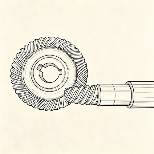
A Hypoid Bevel Gear is a spiral bevel gear variant with non‑intersecting, non‑parallel shafts, featuring an axis offset where the pinion axis lies above or below the crown gear centerline.
In kinematics, Hypoid Bevel Gears bridge spiral bevel gears (intersecting axes, rolling contact) and worm gears (non‑intersecting, high sliding contact). The offset introduces combined rolling and sliding motion along tooth profiles, enabling smooth torque transmission and greater design flexibility in space‑constrained assemblies.
Why Choose Hypoid Bevel Gears?
Greater Single-Stage Reduction Ratio
While standard bevel gears are generally restricted to reduction ratios of 6:1 or lower, Hypoid Bevel Gears can reliably achieve ratios up to 10:1 in a single stage.
High Torque Density & Quiet Operation
The axis offset allows for a larger pinion diameter and an increased spiral angle compared to equivalent spiral bevel gears.
Compact Space Saving
The physical offset of the axes allows the input and output shafts to pass each other on different planes rather than intersecting.
FAQ
They must be supplied strictly as matched pairs. Replacing only one worn gear and mating it with an old counterpart will alter the contact pattern due to the precision required by the offset-axis geometry.
Prototypes (1–5 sets): 3–4 weeks (DFM review, tooling, machining, heat treatment, grinding, CMM inspection). Small-to-medium batches (50–500 sets): 6–8 weeks, mainly driven by CNC grinding queue times and carburizing cycles. A binding timeline is provided in our formal quotation.
The helix hand depends on shaft offset direction and input/output rotation vectors. For example, in a standard layout with pinion offset below the ring gear, a left-hand ring gear pairs with a right-hand pinion. Our engineering team will verify and confirm the correct helix hands during the DFM phase before production.