Gear Shaft
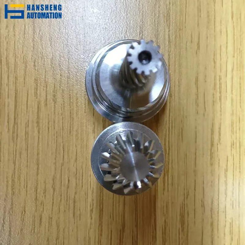
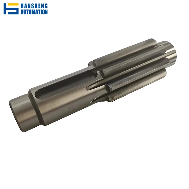
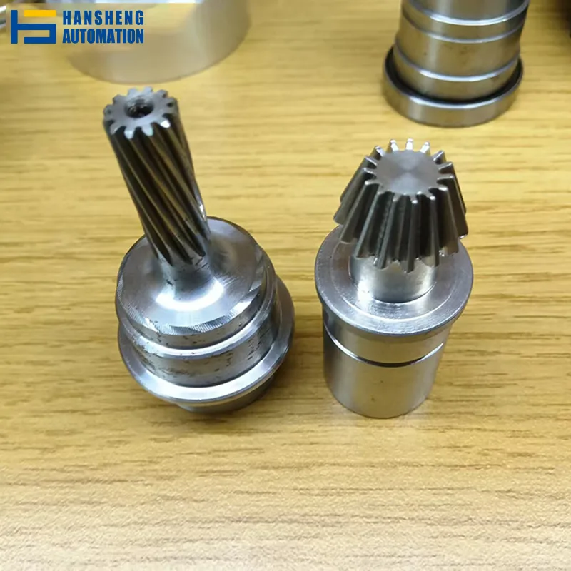
Gear Types: Spur, Helical, Bevel, Internal, Pinion & Spline Shafts
Module Range: M0.1 – M5.0
Max Size: OD Ø300 mm (Up to Ø500 mm) | Custom Length
Precision Grade: Up to ISO / DIN / GB Class 5
Materials: Alloy Steel, Carbon Steel, Stainless, Brass, Plastics
Surface & Finish: Carburizing, Nitriding, Plating, Mirror Finish (Ra 0.2)
Introduction
We manufacture high-precision gear shafts and pinion gear shafts strictly to your CAD drawings and technical specifications. Our end-to-end custom gear shaft manufacturing process covers CNC turning, gear hobbing, heat treatment, and surface grinding to achieve precision up to DIN/ISO Level 5. Upload your drawings today for a rapid quotation and DFM evaluation within 24 hours.
Custom Gear Shaft Specifications & Capabilities
| Feature | Production Capabilities & Parameters |
|---|---|
| Gear Types | Spur gear shafts, Helical gear shafts, Straight bevel gear shafts, Internal ring gears, Pinion gear shafts, Spline shafts. |
| Materials Machined |
|
| Size Range |
|
| Module Range | M0.1 – M5.0 |
| Precision Grade | Up to ISO / DIN / GB Class 5 |
| Surface Finish & Heat Treatment | Carburizing, Nitriding, Black Oxide, Anodizing, Plating, Precision Grinding & Polishing (Mirror finish down to Ra 0.2) |
Tailored Gear Shafts for Every Industrial Need
Pinion Gear Shafts
Teeth too close to the shoulder for conventional hobbing? As an experienced pinion gear shaft manufacturer, we utilize our Kashifuji KPS30 power skiving machine to machine integral pinion shafts—especially where gear teeth sit close to shaft shoulders. Power skiving handles both internal gears and external pinion teeth with equal precision, delivering 3–5×faster processing than gear shaping while maintaining ISO Class 5–7 accuracy. Cycle times drop significantly without compromising batch-to-batch consistency.
Heavy-Duty Spline Shafts
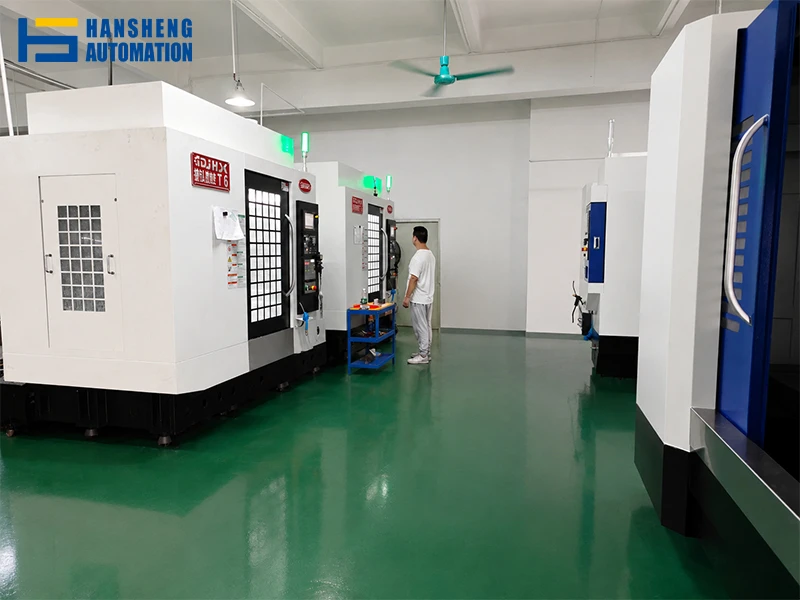
We employ Ningjiang YK3610IV CNC horizontal gear hobbing machines, capable of handling low tooth-count splines with profile errors controlled within 0.015–
0.02 mm (GB Class 6–7, CMM-verified). Supported by large horizontal machining centers (max envelope 2100×1060 mm), we produce heavy-duty shafts for construction machinery, tractors, and industrial drivetrains. For tighter tolerances, post-process gear grinding refines spline profiles down to≤ 0.005 mm.
Stepped Gear Shafts
We produce multi-diameter stepped gear shafts requiring strict coaxiality across complex shaft profiles. Utilizing multi-tasking CNC turn-mill centers, 5-axis machining centers, and Seibu M50B wire EDM equipment, we hold standard turning/milling tolerances of±0.01 mm and precision grinding tolerances down to±0.005 mm to ensure exact concentricity and axial alignment.
Our Proven Gear Shaft Manufacturing Process
Taking one of our real-world production cases as an example—a heavy-duty 45 steel gear shaft engineered to DIN 6 precision,here is a simplified breakdown of our complete manufacturing workflow. Discover how we overcome heat-treatment distortion and concentricity challenges through a strategic three-stage heat treatment process, precise stock allowance management (0.3 mm), and center hole re-grinding.
DFM & Material Normalizing
Rough Turning & Quenching/Tempering
Finish Turning & Center Hole Establishing
CNC Gear Hobbing & Localized Hardening
Center Hole Re-grinding & Journal Grinding
Tooth Surface Grinding & Final Inspection
1: DFM & Material Normalizing
Action: Comprehensive DFM CAD analysis and raw material pre-treatment.
Following initial bar stock cutting, the blank undergoes normalizing to refine its grain structure, improve machinability, and relieve internal stress.
2: Rough Turning & Quenching/Tempering
Action: Rough turning of main contours while leaving a 2.0 mm stock allowance.
Bulk quenching and tempering is applied to achieve a hardness of 250–270 HBW, endowing the core with high toughness and torsional strength while leaving sufficient material to accommodate thermal distortion.
3: Finish Turning & Center Hole Establishing
Action: Finish turning of stepped journals, leaving a 0.3 mm allowance for final grinding.
Precision machining of B2.5 center holes at both ends establishes a unified, strictly coaxial datum reference for all subsequent grinding operations.
4: CNC Gear Hobbing & Localized Hardening
Action: Tooth cutting on high-precision CNC hobbing machines (leaving a 0.2 mm allowance for gear grinding).
High-frequency induction hardening is applied strictly to the tooth flanks to achieve 48–52 HRC, creating an optimal combination of a hard, wear-resistant surface and a tough, shock-absorbing core.
5: Center Hole Re-grinding & Journal Grinding
Action: Re-grinding center holes followed by cylindrical grinding under double-center mounting.
Center holes are re-ground first to eliminate thermal distortion. The bearing journals are then ground in a single setup to φ30g6 tolerance (Ra 0.8 μm), guaranteeing strict concentricity between both bearing seats.
6: Tooth Surface Grinding & Final Inspection
Action: CNC gear grinding referenced off the ground bearing journals.
Final grinding removes quenching distortion to achieve DIN 6 / ISO Grade 6 gear accuracy (profile and runout deviations within 9 μm). Every batch is delivered with full CMM and gear inspection reports.
Deep Dive / Case Study
Want to see the complete 14-step machining breakdown and technical details?
Read the Full Gear Shaft Machining Case Study ➔
Precision Guaranteed: Our Quality Inspection
At Hansheng Automation, every custom gear shaft undergoes multi-stage, rigorous inspection to eliminate dimensional discrepancies and ensure total drawing compliance:
- Gear Measurement System: Verifies tooth profile error (Fα), lead/helix error (Fβ), and total cumulative pitch error (Fp) against specified DIN/ISO accuracy grades.
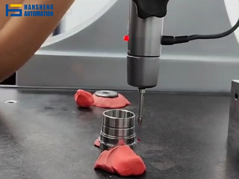
- Coordinate Measuring Machine (CMM): Executes full-dimensional checks, maintaining inner diameter (ID), outer diameter (OD), and thickness tolerances within ±0.01 mm.
- ZEISS Precision Bore Inspection: Leverages high-precision probe compensation to achieve H6 tolerance for inner bores (≤Φ100 mm controlled within ±0.008 mm).
Complete Quality Documentation
To guarantee full traceability, every shipment includes a complete quality documentation package:
- Material Certificates (chemical composition & mechanical properties)
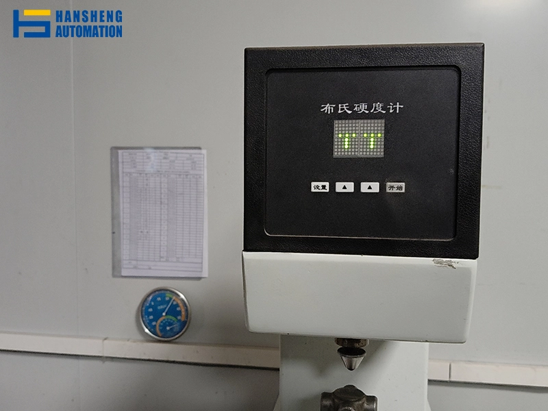
- Heat Treatment Reports (surface hardness, core hardness & case depth)
- Full Dimensional Inspection Reports (raw CMM measurement data)
- Gear Profile & Lead Error Reports (K‑Chart analytical inspection curves)
FAQ
We accept 3D CAD models in STEP (.step, .stp) and IGES (.igs) formats, alongside 2D engineering drawings in PDF, DWG, or DXF for tolerance specifications, surface finish callouts, and material requirements.
Yes. We offer reverse engineering services using Coordinate Measuring Machines (CMM) and gear profile analyzers to extract exact gear tooth parameters, module specifications, and shaft dimensions directly from your physical sample.
We offer flexible MOQs tailored to your project stage—from 1-piece prototypes and low-volume trials to high-volume OEM production runs.
Our gear teeth achieve up to ISO/DIN/GB Grade 5 precision. For critical shaft dimensions, CNC turning and milling holds±0.01 mm, precision cylindrical grinding achieves±0.005 mm, and mirror-finish grinding reaches tolerances down to±0.002 mm.
For rapid prototypes and sample orders, our standard lead time is 7–10 working days (depending on heat treatment requirements). For batch production, lead times typically range from 3 to 4 weeks. Expedited fabrication options are available for urgent project deadlines.
To eliminate rust and handling damage during transit, all shafts undergo ultra-sonic cleaning and heavy-duty anti-rust oil dipping. Tooth profiles are fitted with protective plastic mesh caps, vacuum-sealed in VCI anti-rust bags, and shipped in custom foam-lined wooden crates.


