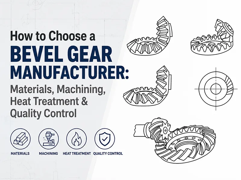
How to Choose a Bevel Gear Manufacturer: Materials, Machining, Heat Treatment & Quality Control
Blog 2026-08-13
What Should You Expect from a Bevel Gear Manufacturer?
When evaluating bevel gear suppliers, look beyond the machine list. Process control, not just tooth cutting, separates capable shops from the rest. Four areas distinguish them:
- Drawing interpretation. Can they identify critical dimensions like mounting distance, face cone angle, and reference surfaces from your print? Do they flag conflicts between design intent and manufacturability?
- Datum and machining control. Do they establish datums consistent with design, assembly, and inspection references? Poor datum control produces teeth that measure correctly but fail to assemble.
- Material and heat treatment capability. Do they match material grade to working conditions? Can they execute carburizing, quenching, or induction hardening with documented cycle parameters?
- Inspection capability. Do they measure not only tooth geometry but also hardness, case depth, and surface roughness? Do they use gear testers or CMM?
A capable shop controls the relationship between gear geometry, reference surfaces, heat treatment, and final inspection. It does not simply cut the teeth.
How Is a Bevel Gear Prepared for Tooth Machining?
Tooth cutting consumes most of the attention, but poor blank preparation ruins more gears than dull cutters do. A supplier that rushes the blank stage will chase geometry errors through the entire production run. Before any tooth is cut, the blank must establish stable, repeatable reference surfaces.
Gear Blank Preparation
Blank preparation differs between shaft-type and disc-type gears, but the surfaces we control remain the same: end face, bore, center hole, shaft journal, and front/rear cone.
For a bevel gear shaft, we machine the end faces, drill the center holes, then rough and finish turn the blank on a lathe. For a disc-type bevel gear, we bore the hole, face the end, and turn the front and rear cone surfaces, then flip the part to machine the opposite end. Every cut references the same established centers or bore axis.
These surfaces establish the foundation for subsequent machining. If the bore runs more than 0.01 mm out of round, or if the end face shows more than 0.015 mm runout relative to the bore axis, tooth grinding cannot compensate. The error propagates directly into the gear tooth orientation and mounting distance.
Why Datum Selection Matters
Some shops select convenient clamping surfaces for the blanking operation, then switch to different references for tooth cutting. That breaks the datum chain.
Our shop rule aligns with engineering fundamentals: the machining datum should match the design datum, assembly datum, and inspection datum as closely as possible. For a bore-mounted bevel gear, we rough and finish the bore to IT7 first, then use that bore to locate the part for turning the OD, end faces, and cone surfaces. The bore serves as the master reference throughout.
Why this discipline? A bevel gear can have perfect tooth geometry, correct pressure angle, ideal spiral, spot-on index, and still fail assembly if the reference relationships are poorly controlled. Mounting distance shifts. Backlash scatters. The pinion rides too deep or too shallow in the ring gear mesh. We have scrapped entire batches from outside vendors who delivered beautiful tooth profiles but ignored the bore-to-face perpendicularity callout. The teeth measured great. The assemblies failed.
Insist that your supplier defines the datum strategy before the first blank hits the lathe. Ask them: Which surface locates the part for tooth cutting? How do you verify that reference surface after the heat treatment? If they cannot answer without flipping through a setup sheet, move on.
Straight vs Spiral Bevel Gear: What Should Buyers Specify?
Most buyers specify a gear type out of habit, not analysis. The choice between straight and spiral affects tooling, cycle time, load capacity, and assembly behavior. When you send an inquiry to a spiral bevel gear manufacturer or a shop that specializes in straight bevel gears, you need to state more than just “bevel gears.” You need to define the tooth form explicitly.
Straight Bevel Gear
A straight bevel gear carries the simplest tooth geometry. The teeth are straight and tapered, with the axes of the pinion and gear intersecting at the cone apex. This basic structure makes straight bevel gears easier to cut on conventional machines and more forgiving to inspect with simple fixtures. They produce a characteristic impact as each tooth engages. This is acceptable for low-speed applications, but the vibration and noise rise quickly with RPM. For hand-fed machinery, low-speed drives, or manual transmissions, a straight tooth design works. For anything spinning past 1000 RPM, expect chatter and shorter fatigue life.
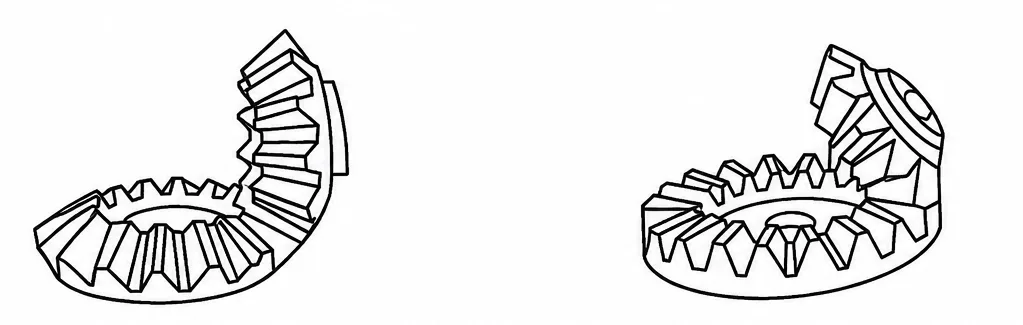
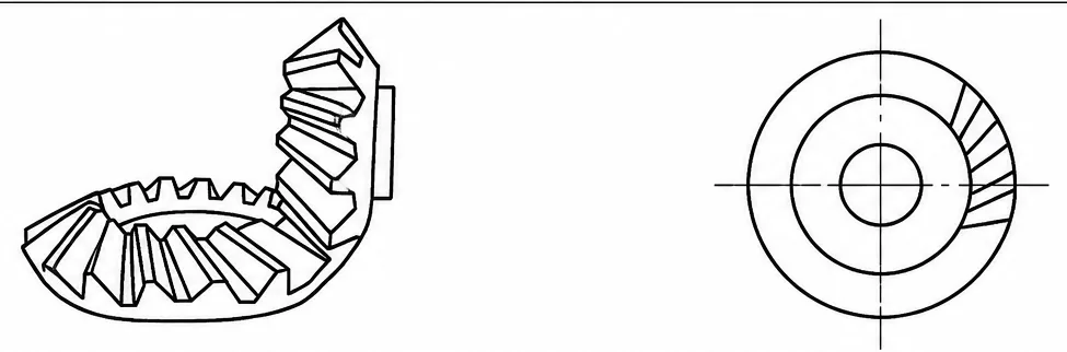
Spiral / Curved-Tooth Bevel Gear
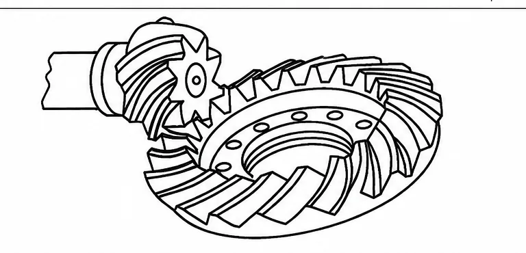
A spiral bevel gear uses curved or oblique tooth traces. The spiral tooth engages gradually rather than slamming into mesh, which delivers smoother transmission and reduces vibration. These gears handle higher loads at higher speeds. In a matched set, the pinion and gear have equal spiral angles but opposite hands, left-hand and right-hand, to roll through mesh properly.
Specifically, spiral bevel gears (including the arc-tooth and extended epicycloid varieties) are standard in automotive drive axles, machine tool spindles, and aerospace transmissions where speed and torque density matter. The curvature also allows higher contact ratios, meaning more teeth share the load at any instant. That geometry demands specialized cutting machines (Gleason, Klingelnberg, or Oerlikon) and skilled setup. Not every supplier has this capability.
| Requirement | Straight Bevel | Spiral Bevel |
|---|---|---|
| Tooth form | Straight, tapered | Curved / spiral trace |
| Transmission smoothness | Standard, stepped engagement | Higher, gradual engagement |
| High-speed suitability | Limited; vibration rises with RPM | More suitable; stable at speed |
| Typical applications | Low-speed drives, hand tools, differentials | Automotive axles, machine tools, high-torque drives |
When you specify, confirm which type your supplier actually supports. Some shops advertise “bevel gears” but only cut straight teeth on older equipment. If your application requires spiral, verify the machine platform and cutting method (face-milling vs. face-hobbing) before placing the order.
How Material and Heat Treatment Affect Bevel Gear Performance
Selecting the right material is not a lookup-table exercise. The same gear drawing produced in 20CrMnTi versus 40Cr versus QT600-3 will behave differently under load, wear differently at the contact pattern, and respond differently to heat. A heat treatment schedule that works for one alloy can ruin another. Buyers often specify “hardened to 58 HRC” without linking that requirement to the material’s hardenability or section size. That is a mistake.
Material Selection Depends on Working Conditions
Material choice starts with the duty cycle. Our shop categorizes bevel gear material into four broad families, each with distinct boundaries:
- Low-carbon structural steel / low-carbon alloy steel (e.g., 20Cr, 20CrMnTi, 20MnVB). These alloys respond to carburizing. They develop a hard, wear-resistant case while retaining a tough core. Specify these for impact loads and high tooth bending stresses.
- Medium-carbon structural steel / medium-carbon alloy steel (e.g., 45, 40Cr, 35SiMn). These through-harden or respond to induction hardening. They suit moderate loads where carburizing adds unnecessary cost and cycle time.
- Cast steel (e.g., ZG270-500, ZG310-570). For large, coarse-pitch gears where forging economics break down. Mechanical properties lag behind wrought alloys, so derate accordingly.
- Cast iron / ductile iron (e.g., HT200, HT300, QT400-18, QT600-3). Low-speed, low-stress applications. QT600-3 approaches mild steel strength but lacks the toughness for shock loading.
The principle is straightforward: material selection must consider working conditions, accuracy requirements, and heat-treatment processability. You cannot specify a 56–62 HRC surface hardness on a 45 steel gear without surface hardening. The core lacks the hardenability to support that case. Likewise, specifying a low-carbon alloy without a carburizing furnace in the supply chain guarantees missed specifications. We routinely reject inquiries that pair an alloy with an incompatible heat treatment because the parts will fail validation, regardless of how well we cut the teeth.
20CrMnTi Carburizing Example
Consider this production-proven cycle. 20CrMnTi is arguably the most common carburizing grade in automotive and machine tool bevel gears. Below is our standard process for a pinion or ring gear requiring a 1.2–1.6 mm effective case depth.
Engineering Example – 20CrMnTi Carburized Bevel Gear
| Parameter | Specification |
|---|---|
| Material | 20CrMnTi |
| Carburizing temperature | 930°C |
| Strong carburizing stage | 2.5 hours |
| Diffusion stage | Controlled duration based on target case depth |
| Pre-cool temperature (for direct quench) | 840°C, hold 30 minutes |
| Quenching medium | Oil (press quench for ring gears) |
| Tempering temperature | 200°C |
| Tempering hold time | 120 minutes |
| Cooling after temper | Air |
| Tooth surface hardness | 58–64 HRC |
| Core hardness | 33–48 HRC |
| Effective case depth | 1.2–1.6 mm |
We require cleaning before carburizing and before tempering. Oil residue or contaminants on the surface produce soft spots or uneven case depth. Shot peening for 30–50 minutes after tempering closes the loop. It imparts compressive residual stress at the tooth root, improves surface finish, and exposes any subsurface porosity before final inspection.
This specific cycle has run on thousands of automotive drive pinions and machine tool spindle gears. It works because the material, temperature, time, quench, and temper are matched to the section thickness and the required hardness gradient. Change any variable, section thickness beyond 80 mm, or an oil quench that fails to extract heat fast enough, and you lose case depth or develop excessive retained austenite.
Other Heat Treatment Options
Carburizing is not the only route. For gears that do not need a deep, wear-resistant case, several alternatives exist:
- Normalizing refines grain structure after forging or rough machining. For low-grade steels (carbon below 0.5%), normalizing improves machinability more effectively than annealing. We use it as a preparatory step, not a final treatment.
- Quenching and tempering through-hardens medium-carbon and medium-alloy steels. It develops uniform hardness across the tooth section, but core and surface hardness end up similar. Use this when bending fatigue dominates contact fatigue.
- Induction hardening provides selective surface hardening for medium-carbon steels like 45 or 40Cr. The gear tooth tips and flanks reach 45–55 HRC while the core stays at the quenched-and-tempered strength level. Effective for medium-duty applications where carburizing adds unnecessary cost.
- Nitriding produces a thin, extremely hard case (typically 900–1100 HV) without quenching distortion. The low processing temperature preserves core properties and dimensional stability. The downside is shallow case depth and longer cycle times (20–50 hours).
- Annealing removes residual stress from prior operations and improves ductility. Rarely used for final gearing, but valuable as an intermediate step before heavy machining.
Each of these heat treatment routes addresses a specific failure mode: wear, pitting, tooth breakage, or dimensional instability. A capable supplier will recommend the route that matches your loading conditions, not the one they run most often. If a vendor offers only one heat treatment option for all inquiries, they are optimizing their furnace utilization, not your gear performance.
How Does a Bevel Gear Manufacturer Control Quality?
Quality control in bevel gear production is not a final inspection step. It is a closed-loop discipline that begins with the first turning operation and ends with a signed report. Many suppliers measure tooth geometry at the end and call it “quality.” That catches gross errors but misses the assembly-killers. A competent shop controls three interconnected domains: reference surfaces, critical gear parameters, and heat treatment validation. Miss any one, and the gear fails in the housing, not on the CMM.
Control the Reference Surfaces
We treat reference surfaces as the foundation of the inspection plan, not an afterthought. Bore, end face, and shaft journal diameters, roundness, and perpendicularity get measured before tooth cutting begins and again after heat treatment. The datum strategy extends from machining through inspection: we locate the gear on the same bore or center holes during final inspection that we used for tooth cutting. That ensures our measurements reflect real assembly conditions, not ideal fixture conditions that disappear when the gear ships.
For a bore-mounted bevel gear, we verify:
- Bore diameter to IT7 tolerance (typically H7 or better).
- End face runout relative to the bore axis—hold this within 0.015 mm for automotive grades.
- Shaft journal concentricity and cylindrical form if the gear runs on bearings.
If the reference surfaces drift during heat treatment, we do not “correct” them with soft jaws that induce new errors. We reject the blank or mandate a grinding operation that re-establishes the datum before tooth finishing. Control the reference surfaces, and the teeth have a fighting chance at proper mesh.
Control the Critical Gear Parameters
Print callouts tell us exactly what to measure. For a typical bevel gear drawing, the manufacturer must control and document:
- Dimensional tolerance – Outside diameters, root diameters, and face widths within specified limits.
- Position tolerance – Runout of the tooth pitch circle relative to the bore axis. AGMA class 9 or better typically demands runout under 0.05 mm.
- Mounting distance – The location of the gear face relative to the intersection point of the pinion and gear axes. This value dictates pinion position in the assembly. If the mounting distance drifts, the contact pattern shifts to the tooth edge.
- Face cone angle – The outer cone angle that defines tooth tip geometry. Errors here produce tooth tip interference or excessive clearance.
- Surface roughness – Flank roughness (Ra) directly affects scuffing resistance. For ground bevel gears, Ra 0.8–1.6 µm is standard. For cut gears, Ra 3.2 µm or higher may be acceptable for low-speed applications.
- Hardness and case depth – Verified separately during destructive or non-destructive testing.
We run these checks on a gear measuring center or CMM with a rotary table. Single-flank rolling tests catch composite errors, tooth-to-tooth spacing and runout, that individual probe measurements miss. A gear can pass individual tooth profile checks and still fail the rolling test due to index errors. We reject based on rolling test results before we even generate the full inspection report.
Verify Heat Treatment
Heat treatment validation is where many suppliers cut corners. They check surface hardness with a portable tester and call it done. That is insufficient. We demand full verification of both hardness and case depth, with documented traverse data.
For the 20CrMnTi carburizing case we discussed earlier, verification includes:
- Surface hardness: 58–64 HRC on the tooth flanks and tips. We use a Rockwell tester with a flat anvil that supports the gear correctly. Test at least three teeth, two positions per flank.
- Core hardness: 33–48 HRC, measured on a sectioned tooth or on a separately processed test coupon that follows the gear through the same furnace load.
- Effective case depth: 1.2–1.6 mm. We cut a transverse section, etch it, and measure the depth from the surface to the 550 HV boundary. If the case depth falls below 1.2 mm, the gear will pit in service. If it exceeds 1.6 mm excessively, the case may become brittle and spall.
Every production lot gets at least one destructively tested sample for case depth verification unless we use a process-monitoring system proven to correlate non-destructive measurements (eddy current or Barkhausen) to depth results. We document the hardness traverse curve, not just the endpoints, so the buyer sees the gradient. A shallow case or a soft core directly compromises tooth bending fatigue, regardless of how accurately we cut the involute.
Correct material selection supports the heat treatment; inspection validates both. When they do not align, the shop owes you a root-cause analysis, not a re-run on the same flawed process.
What Information Should You Send to a Bevel Gear Manufacturer?
Incomplete inquiry packages waste everyone’s time. We receive RFQs that say “need bevel gear, please quote” with no drawing, no material spec, and no accuracy requirement. That forces us to send a list of clarifying questions. The clock starts ticking then, not when you sent the email. A shop cannot evaluate process feasibility without basic inputs. If you want a serious proposal, send a complete package upfront.
Here is the checklist we actually use internally to triage new inquiries. Send these items, and we can assess manufacturability and cost within one business cycle:
| Requirement Item | Essential Details to Provide |
|---|---|
| Drawing & Data | Dimensioned 2D print with tolerances and tooth data (pressure/spiral angle, face width, pitch dia.). *3D models are supplemental. |
| Gear Type | Straight, spiral, or other. Specify if ordering matched sets (pinion + ring) or individual parts. |
| Material | Specific grade (e.g., 20CrMnTi, 40Cr) OR describe load conditions for a recommendation. |
| Heat Treatment | Treatment method (e.g., carburizing), surface/core hardness range, and effective case depth. |
| Accuracy Grade | Reference standard (AGMA, DIN, ISO, GB) and list explicit custom tolerances on the print. |
| Mounting Distance | Mandatory State exact distance to pitch cone intersection for CMM contact pattern validation. |
| Quantity | Initial order lot size and annual volume (determines tooling and per-piece cost). |
| Inspection & QC | Required tests (CMM, hardness, rolling test, NDT) and reports (e.g., First-Article Inspection, 3rd party witness). |
The more complete the drawing and technical requirements, the faster the manufacturer can evaluate process feasibility and quotation conditions. Incomplete inputs lead to assumptions, and assumptions generate either padded quotes or optimistic prices that fail when we discover the missing spec during production.
One practical tip: if you have an older gear that performed adequately but lacks a drawing, send the physical part to a bevel gear supplier for reverse engineering. Scanning and measuring an existing gear takes less time than rebuilding the design from scratch. Just be prepared to verify that the original gear actually met the requirements. We have reverse-engineered parts that were out of spec from the factory, and copying the error only repeats the failure.
FAQ
Common grades include 20CrMnTi, 20Cr, 40Cr, 45, cast steels like ZG310-570, and ductile irons such as QT600-3. Selection depends on load, required hardness, and heat treatment method.
Typical processes: carburizing (for case hardness 58–64 HRC), induction hardening, through-hardening (quench + temper), nitriding, and normalizing. The choice is dictated by material grade and performance targets.
Straight bevel gears have straight teeth, engage abruptly, and suit low speeds. Spiral bevel gears have curved teeth, engage gradually, and run smoother at higher speeds. They require specialized cutting equipment.
Provide: dimensioned drawing/3D model, gear type, material grade, heat treatment specification, accuracy class (AGMA/DIN/ISO), mounting distance, quantity, and inspection requirements. Complete inputs accelerate feasibility assessment and quoting.