Straight Bevel Gear: Design, Structure, Manufacturing and Applications
Blog 2026-08-18
What Is a Straight Bevel Gear?
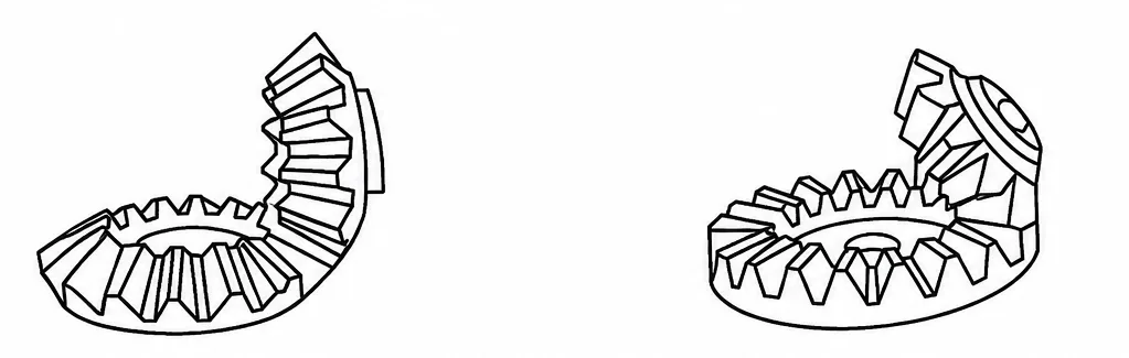
A straight bevel gear transmits motion and power between intersecting shafts. The “straight” designation refers to its tooth form: the teeth are straight-sided and project radially toward the cone apex, similar to a spur gear profile wrapped onto a conical blank. Extend the tooth centerlines inward, and they converge at the same point where the two shaft axes intersect. This geometric constraint dictates everything from blank geometry to cutter selection.
In production, we machine these gears for differentials, industrial transmissions, and machine-tool drives. Their job is straightforward: redirect rotation by a fixed angle—typically 90°—while maintaining a constant angular velocity ratio. Unlike cylindrical gears, where the pitch cylinder defines the geometry, the pitch cone governs the entire tooth profile. The cone angle determines the gear ratio directly, and the straight tooth form requires simpler setups than spiral bevels. That simplicity, however, introduces shop-floor challenges. Runout control and contact pattern consistency demand careful setup, which we will cover in later sections.
Basic Structure of a Straight Bevel Gear
The structural logic of a straight bevel gear rests on three fixed principles:
- Intersecting axes: The pinion and gear axes intersect at a single cone apex. No offset, no skew.
- Conical pitch surface: The pitch surface is a cone, not a cylinder. Tooth depth and chordal thickness vary progressively from the outer face to the inner cone.
- Straight tooth traces: Each tooth follows a straight path converging toward the apex.
When the pitch cone angle of the larger gear reaches 90°, the gear becomes a flat crown gear—a theoretical reference used in generating cutters for other bevel gears. Exceed 90°, and the configuration shifts to an internal bevel gear set. For shop-floor work, external straight bevel pairs remain the primary concern, with pitch cones rolling together without slipping to transmit torque across intersecting shaft lines.
Why Are Straight Bevel Gears Different from Cylindrical Gears?
The difference is not merely about shape—it changes how you establish setups and inspect parts. A spur gear operates on a cylindrical pitch surface. Every tooth along the face width is identical, and the gear meshes with its mate on parallel axes. Concentricity and runout are the primary setup concerns.
A straight bevel gear discards that simplicity. The pitch surface tapers, so tooth depth and chordal thickness vary continuously across the face width. The gear ratio depends on the ratio of pitch cone angles, not just tooth counts. This conical geometry shifts the entire manufacturing philosophy: the machining datum, mounting distance, and face cone angle directly govern the final tooth contact pattern. Any deviation in the reference surfaces shifts the pinion’s position relative to the gear center, altering backlash and bearing contact. Establish precise datums before tooth cutting—it is a prerequisite for a stable, repeatable gear set.
Straight Bevel Gear Structure and Key Design Requirements
Specifying the number of teeth and the module barely addresses the real design work. The conical geometry introduces interdependent parameters that determine whether the gear set runs quietly, wears evenly, or fails prematurely. In our experience, the difference between a problematic batch and a reliable run traces back to how thoroughly these five technical requirements were defined before the first chip flew.
The Five Key Technical Requirements of a Bevel Gear
Every complete straight bevel gear drawing must explicitly address these five categories. Omitting or loosely defining any one of them invites scrap or field failures.
1. Gear Reference Surfaces
The reference surfaces consist of the locating datum (where the part mounts to the fixture or shaft), the measuring datum (used for quality inspection), and the assembly datum (which mates with the mating part’s corresponding surface). In practice, these are often the same physical feature—typically the bore or the back face. We always verify that the drawing identifies which surface serves which function. Ambiguity here leads to inspection disputes.
2. Dimensional and Positional Tolerances
These are not standalone numbers. The tolerance on the bore diameter, for instance, directly affects the clearance on the assembly shaft, which in turn shifts the pinion’s position relative to the gear center. Positional tolerances—such as runout of the pitch cone relative to the bore axis—control the geometric relationship that preserves the tooth contact pattern. We treat them as interconnected constraints rather than isolated dimensions.
3. Mounting Distance
This parameter determines the exact spatial position of the gear within the assembled system. It is the distance from a specified reference surface (usually the back face of the gear) to the intersection point of the shaft axes. In production, we check mounting distance on a gear tester. If it drifts out of tolerance, the entire tooth contact pattern shifts toward the toe or heel, concentrating stress and shortening service life. This is one of the first dimensions we audit on incoming gear blanks.
4. Face Cone Angle
The face cone angle defines the outer boundary of the tooth surface and directly ties to the pitch cone geometry. It controls where the tooth tip terminates and influences tooth strength. We machine this angle carefully during blank preparation—any deviation alters the face width available for contact and compromises the specified gear ratio.
5. Surface Roughness and Heat Treatment
Roughness directly affects sliding friction and lubrication retention on the tooth flanks. We typically target Ra 1.6 µm or finer on the active profiles for moderate-duty applications. Heat treatment determines the final hardness and residual stress state. The drawing must specify not only the hardness value but also the case depth where applicable—grinding allowances depend on the distortion expected after quench.
Why Datum Selection Matters in Straight Bevel Gear Design
The accuracy of a straight bevel gear starts with its machining datum. Design datum, assembly datum, and measurement datum must coincide as closely as possible. When they do not, you introduce a chain of stacking errors that no precision gear cutter can compensate for.
Consider a typical bore-type straight bevel gear. The bore serves as the primary locating and measuring surface. Here is the sequence we follow:
- Rough machine the bore, end face, and front/rear cone surfaces, leaving stock for finishing.
- Finish the bore to IT7 tolerance. IT7 provides sufficient accuracy for the mandrel or arbor that will locate the part during subsequent operations.
- Mount the gear on a precision arbor using the finished bore as the locating surface.
- Machine the external diameter, the opposite end face, and the front and rear cone surfaces in this same setup.
Why this sequence? Finishing the bore first establishes a stable, repeatable reference axis. When we then machine the cone surfaces using that bore as the datum, runout and misalignment are minimized. The front and rear cones, the face cone, and the back face all reference that IT7 bore. This eliminates the variability introduced by repeatedly re-chucking the workpiece. We have seen many shops skip the IT7 bore finish before tooth cutting, only to chase taper and wobble issues during gear inspection.
What Should Be Defined on a Straight Bevel Gear Drawing?
The engineering drawing must translate the five technical requirements into measurable, inspectable callouts. Below is the baseline checklist we require before releasing any straight bevel gear to the production floor:
| Drawing Requirement | Engineering Purpose |
|---|---|
| Reference datum | Establishes the master surfaces for machining setup and final inspection alignment |
| Bore / shaft journal | Defines the primary locating surface; must include IT7 tolerance for bore-guided setups |
| Mounting distance | Controls the axial position of the gear relative to the shaft axes intersection point |
| Face cone angle | Sets the outer geometry of the tooth surface and preserves the specified face width |
| Dimensional tolerance | Governs individual feature sizes (bore, outer diameter, thickness) with clear maximum material conditions |
| Position tolerance | Controls coaxiality, runout, and perpendicularity between the bore, cone, and back face |
| Surface roughness | Specifies Ra / Rz values for the tooth flanks, back face, and bore to manage friction and fit |
| Heat treatment | Defines the hardness range, case depth (for carburized parts), and the sequence (pre- or post-tooth cutting) |
With these requirements clearly called out, the manufacturing engineer can select the correct machines, fixtures, and inspection gauges. The drawing becomes a contract between design and production—not just a geometric sketch.
How Are Straight Bevel Gears Manufactured?
The path from a raw forging or bar stock to a finished straight bevel gear follows a disciplined sequence. We do not treat it as a collection of independent operations. Each step—blank preparation, datum establishment, rough cutting, heat treatment, and finishing—directly influences the next. Deviate from the sequence, or rush any intermediate stage, and the tooth contact pattern will show it on the inspection bench.
Step 1 — Gear Blank Preparation
The blank preparation strategy splits cleanly based on the part geometry. For a bevel gear shaft, the workpiece has integral journals. We start by facing both ends to establish parallel reference planes, then spot the center holes. The center holes support the shaft between centers for subsequent turning operations. The sequence is:
Face Ends → Spot Center Holes → Rough Turn Major Diameters → Finish Turn Bearing Journals and Cone Surfaces
For a bevel gear blank—the ring-type gear without an integral shaft—the approach differs. The bore becomes the primary feature, so we prioritize it early:
Rough Bore → Face Back Face → Rough Front Cone → Flip Part → Machine Rear Cone and Remaining External Features
We leave approximately 0.5 mm to 0.8 mm of stock on all finished surfaces during this stage. The goal is a stress-relieved, geometrically sound blank ready for the datum preparation step.
Step 2 — Establish the Machining Datum
Blank preparation is not merely about roughing out metal. Its true purpose is to generate a set of reliable reference surfaces that will locate the gear throughout tooth cutting and inspection. If the blank is out of square or the bore is tapered, every subsequent operation compounds that error.
We practice a strict sequence for the bore-type gear. The bore is roughed, then finished to IT7 tolerance using a precision internal grinder or a fine-boring head. Why IT7? This tolerance band provides the necessary fit for a ground arbor or expansion mandrel without excessive clearance. Once the bore measures within IT7, we mount the blank on the arbor and machine the back face, the front cone, and the rear cone in a single clamping. This single-setup approach ensures that the cone surfaces are concentric with the bore axis and square to the back face within a few microns. We treat the bore and back face as the master pair—they define the X, Y, and Z references for every subsequent setup.
Step 3 — Rough Tooth Machining
With the datums established, we move to the gear cutting machine—typically a Gleason or Klingelnberg bevel gear generator for production runs. Rough tooth machining establishes the initial tooth geometry. The cutter engages the blank and generates the straight tooth flanks.
We do not aim for final dimensions here. The roughing pass leaves a uniform stock allowance—typically 0.15 mm to 0.25 mm per flank—for the finishing operation. This allowance compensates for any minor distortion during subsequent heat treatment and provides clean stock for the final cutter pass. We monitor the roughing cycle for chatter and tool deflection. If either appears, we adjust the feed rate or workholding rigidity before proceeding.
Step 4 — Gear Heat Treatment
Heat treatment is an integrated step within the overall manufacturing route, not a standalone material process. The sequence for a typical carburized straight bevel gear:
Raw Material → Normalizing (preparatory) → Gear Blank Machining (establish datums) → Rough Tooth Cutting → Carburizing & Quenching → Tempering → Tooth Finishing → Final Inspection
The rough-cut gear enters the furnace with a defined case depth specification. During carburizing, the tooth flanks absorb carbon at elevated temperatures—typically around 930°C for materials like 20CrMnTi. The quench cycle transforms the case to martensite, achieving a surface hardness of 58–64 HRC, while the core retains a tougher structure at 33–48 HRC.
Distortion is unavoidable during quench. We account for this by designing the roughing stock allowance to absorb runout and taper changes without leaving hard scale on the finishing tools. After quenching and tempering (e.g., 200°C for 120 minutes), we perform a shot-peening operation—typically 30 to 50 minutes—to relieve surface tensile stresses and improve fatigue life. Clean the parts before carburizing and again before tempering; residual oil burns into the surface and interferes with the carbon gradient.
Step 5 — Tooth Finishing and Final Inspection
Finishing brings the gear to its final functional geometry. We use a finish cutter or a grinding wheel, depending on the required quality level, to remove the remaining stock from the tooth flanks. Because the part has hardened, we run the finishing operation at conservative speeds to avoid burn marks or micro-cracks.
The final inspection directly verifies the five technical requirements outlined earlier:
- Reference surfaces: Check the bore diameter and back face squareness against the master arbor.
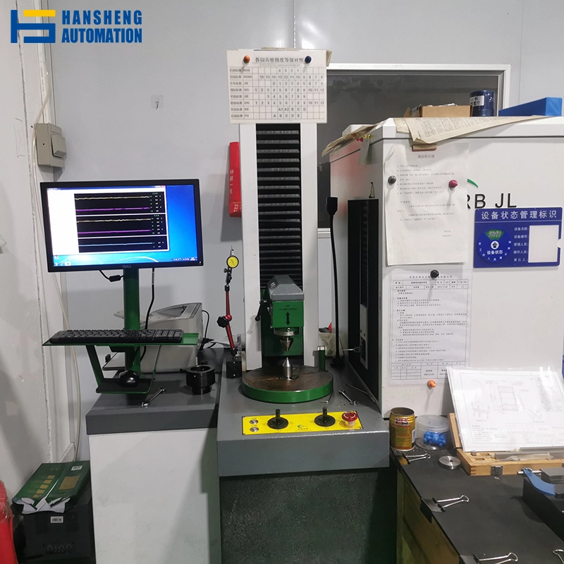
- Mounting distance: Mount the gear on a tester; measure the distance from the back face to the axis intersection point using gauge blocks.
- Face cone angle: Inspect the outer taper angle with a dedicated cone gauge or CMM.
- Surface roughness: Verify the active flanks meet the specified Ra value (typically ≤ 1.6 µm) using a profilometer across multiple teeth.
- Heat treatment condition: Perform a hardness traverse on a test coupon or sacrificial tooth to verify the case depth (e.g., 1.2–1.6 mm) and surface hardness.
The gear passes only when all five categories fall within their specified limits.
Straight Bevel Gear Materials and Heat Treatment
Selecting the right material for a straight bevel gear is not a matter of picking the strongest steel from a table. The choice governs machinability, distortion during heat treatment, and the final load-carrying capacity of the tooth flank. We evaluate three factors on every job: actual working conditions (shock loading, continuous duty, or intermittent operation), required accuracy grade (higher precision demands more stable materials), and heat-treatment processability (some alloys respond predictably to quench; others distort unpredictably). Getting this triage right upfront saves weeks of scrap rework.
Common Carbon and Alloy Steels
For moderate-duty applications where surface hardness below 300 HBW is acceptable, plain carbon steels deliver adequate performance at lower cost.
35 Steel is a workhorse for light-to-medium load gears. Normalized, it runs 150–180 HBW—soft enough for easy machining but limited in wear resistance. Quenched and tempered (Q&T), it reaches 190–230 HBW with improved toughness. We use it for low-speed, low-shock transmissions where tooth bending is the primary concern.
45 Steel offers a wider processing window. In the Q&T condition, it lands at 220–250 HBW, suitable for general machinery gears. When the design calls for higher surface durability, we specify overall hardening to reach 40–45 HRC—this produces a uniform martensitic structure through the tooth cross-section. For applications requiring only wear-resistant flanks with a tougher core, surface hardening (induction or flame) takes the tooth surface to 45–50 HRC while leaving the core at approximately 250–280 HBW. The surface-hardened 45-steel gear is common in machine-tool feed drives where shock loads are minimal but sliding wear is a concern.
Alloy Steels for Higher Performance Applications
When gear duty escalates—higher speeds, heavier loads, or impact conditions—we move to alloy steels. These grades incorporate chromium, manganese, molybdenum, or nickel to improve hardenability and core toughness.
- 40Cr (Q&T): Delivers 250–280 HBW after tempering. The chromium content boosts depth of hardening, making it suitable for medium-duty bevel gears in industrial gearboxes.
- 20Cr, 20CrMo, 20CrMnTi, 30CrMnTi: These low-carbon alloys are designed for carburizing and quenching. The low carbon content keeps the core ductile (typically 33–48 HRC after quench), while the carburized case reaches 56–64 HRC. This combination—hard surface, tough core—is exactly what heavy-duty bevel gears demand. Among these, 20CrMnTi is our most frequently specified grade for automotive and heavy-machinery applications because it responds consistently to the carburizing cycle and maintains good fatigue resistance.
Why Carburizing Is Common for Heavy-Duty Bevel Gears
Carburizing is a targeted solution for specific service conditions, not a default choice. We select it when the gear must withstand both high contact stress and impact loading.
Look at real-world application mapping from production data:
- Automotive drive axles (drive and driven bevel gears): 20CrMnTi → carburize and quench. The pinion sees high-speed rotation and shock loads from clutch engagement; the case hardness resists pitting, while the tough core absorbs impact without fracturing.
- Tractor final drives and construction machinery bevel gears: 20Cr, 20CrMo, 20CrMnMo, 20CrMnTi, or 30CrMnTi → carburize and quench. These machines operate in dirty, high-torque conditions. The carburized case provides wear resistance against abrasive contaminants, and the core prevents tooth breakage during sudden load reversals.
This is the application → material → heat treatment chain that guides our material specifications. We never specify a carburizing grade without also defining the required case depth and core hardness for that particular duty cycle.
Real Heat Treatment Example: 20CrMnTi Straight Bevel Gear
The following process cycle represents a production-proven route for a 20CrMnTi straight bevel gear used in an automotive rear-axle application. We run this cycle routinely and have validated its repeatability across thousands of parts.
| Parameter | Value |
|---|---|
| Material | 20CrMnTi |
| Carburizing temperature | 930°C, strong carburizing for 2.5 hours, followed by diffusion period to achieve gradient case |
| Pre-cooling temperature | 840°C (prior to quench) |
| Quenching medium | Oil (press-quenched to control distortion) |
| Tempering | 200°C, hold 120 minutes, air cool |
| Tooth surface hardness | 58–64 HRC |
| Core hardness | 33–48 HRC |
| Effective case depth | 1.2–1.6 mm |
| Shot peening | Required, 30–50 minutes after tempering |
| Cleaning | Required before carburizing and before tempering |
A gear manufacturer should not specify material and heat treatment independently. The required tooth hardness, core toughness, and case depth must be considered together with the gear’s service conditions. A 20CrMnTi gear running in a mild-duty conveyor drive does not need the same case depth as one handling 500 N·m in a truck differential. Match the case depth to the actual Hertzian contact stress, not to a generic table.
Other Heat Treatment Routes
Not every straight bevel gear requires carburizing. We use these alternative thermal cycles depending on the material and duty:
| Heat Treatment | Primary Purpose | Typical Application |
|---|---|---|
| Normalizing | Refines grain structure, improves machinability of low-carbon steels | Pre-treatment for gear blanks before turning |
| Quenching & Tempering (Q&T) | Achieves a balanced strength-toughness combination across the section | 35/45 steel gears in moderate-duty transmissions |
| Induction / Flame hardening | Produces a hard surface (45–55 HRC) while retaining a softer, tougher core | Large-diameter gears where carburizing is impractical |
| Nitriding | Hardens case via nitrogen diffusion, improves wear and corrosion resistance | Precision gears requiring minimal distortion (nitriding temperature is low) |
The choice among these routes depends on the production volume, the required hardness profile, and the distortion budget. Induction hardening leaves the gear with minimal growth—ideal for finished-bore gears that cannot tolerate post-heat grind allowance. But it cannot match the load-carrying capability of a carburized, shot-peened 20CrMnTi gear.
Straight Bevel Gear vs Spiral Bevel Gear
The choice between a straight and a spiral bevel gear often comes down to the operating envelope. Many engineers assume straight bevels are simply the lower-cost, lower-performance alternative—but the decision should factor in speed, load, noise constraints, and manufacturing capability. Let us compare both configurations based on what we see on the shop floor.
Straight Bevel Gear
The straight bevel gear features teeth that run straight and converge toward the cone apex. The tooth form is straightforward—essentially a spur gear profile wrapped onto a conical pitch surface. This translates to simpler machine setups, fewer cutter variables, and shorter cycle times. We use straight bevels extensively for practical transmission requirements where moderate speeds and loads are the norm. They are forgiving to set up, and tooth contact adjustments are easier to execute compared to curved-tooth designs.
Spiral / Curved-Tooth Bevel Gear
Spiral bevel gears—including both spiral and curved-tooth variants—have teeth that are oblique to the cone element. The tooth trace forms a curve rather than a straight line. This geometry creates a gradual, overlapping tooth engagement: multiple teeth contact simultaneously, reducing shock loading and noise. The feel on the test stand is smoother—no rhythmic thumping as each tooth enters mesh.
Spiral bevel gears handle higher torque capacities for the same size envelope because the curved tooth line increases the contact ratio. They are the default choice for high-speed, high-power drives where noise and vibration must be tightly controlled. However, they come with trade-offs: cutter geometry is more complex, setups are less forgiving, and tooth contact adjustments require more skill. Higher initial tooling and setup costs are the price for smoother transmission.
| Factor | Straight Bevel Gear | Spiral Bevel Gear |
|---|---|---|
| Tooth geometry | Straight, converging to apex | Spiral / curved, oblique to cone element |
| Transmission smoothness | Standard, step-wise tooth engagement | Higher, gradual overlapping contact |
| High-speed operation | Application dependent—suitable for moderate speeds | More suitable—handles high RPM with lower noise |
| Manufacturing complexity | Relatively straightforward; simpler cutter geometry | More complex; specialized cutters and rigorous setup |
| Typical selection logic | Practical, cost-sensitive transmission requirements | Smoother operation, higher speeds, and heavier loads |
Straight bevel gears are not a lower-performance version of spiral bevel gears. The correct choice depends on speed, load, transmission requirements, and manufacturing considerations. For rugged, lower-speed applications where cost and repairability matter, straight bevels are often the smarter choice. For high-speed, high-power drivetrains where smoothness and longevity are critical, spiral bevels justify the added complexity and cost.
Straight Bevel Gear Applications
Straight bevel gears appear wherever intersecting shafts need a simple, rugged torque transfer. We do not see them in every industry, but in the sectors where they dominate, they are nearly impossible to replace with cylindrical or spiral alternatives. Three verticals account for the bulk of our production runs: automotive drivelines, off-highway equipment, and precision machine tools.
- Automotive Applications
- Agricultural and Construction Machinery
- Machine Tools and CNC Equipment
What Should Engineers Check Before Ordering a Straight Bevel Gear?
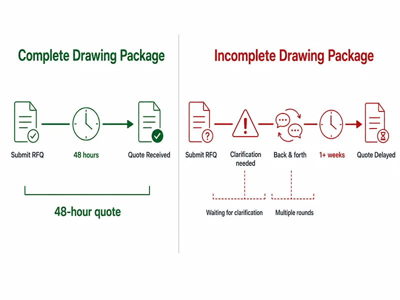
A complete drawing package prevents costly surprises. We have seen too many orders delayed because critical information was missing—or worse, assumed. Before you send a straight bevel gear inquiry to any shop, run through this checklist. It covers the technical details that directly affect manufacturability, cost, and final performance. If any item is unclear on your drawing, clarify it before the quote lands.
Gear Geometry
Confirm the fundamental geometry first. These parameters define the gear’s identity and are non-negotiable for the manufacturer.
- Gear type: Explicitly state straight bevel gear. Do not assume the shop will infer it from the tooth trace. Some suppliers default to spiral if not specified.
- Gear pair relationship: Provide the mating gear’s tooth count, shaft angle, and whether the pair is identical or one is a pinion. The ratio affects cutter selection.
- Shaft arrangement: Specify the intersecting shaft angle—typically 90° but not always. Any deviation from 90° requires custom machine settings.
- Cone geometry: Include the pitch cone angle, face cone angle, and root cone angle. These three define the conical envelope of the tooth surfaces.
If your drawing only shows a side view without a developed cone layout, the setup technician will need to reverse-engineer the cone angles from the tooth data.
Reference and Mounting Requirements
The datums and mounting features determine how the gear will locate in the assembly and how we fixture it during machining.
- Bore or shaft journal: Define the primary locating diameter. If bore-type, specify the tolerance class—IT7 is our baseline for arbor mounting. If shaft-type, provide the journal diameters and the center hole specifications.
- End face: The back face (the flat surface opposite the teeth) often serves as the axial locating surface. Call out its flatness and perpendicularity relative to the bore axis.
- Datum structure: Identify which surfaces are the machining datum, assembly datum, and inspection datum—and confirm they are the same physical features.
- Mounting distance: State the nominal value and tolerance for the distance from the reference end face to the shaft axis intersection point.
- Face cone angle: Re-confirm this value against the cone geometry section.
We recommend drawing a separate datum reference chart on the print, listing each reference surface and its intended function.
Material and Heat Treatment
Material and heat treatment must be specified together, not as separate line items.
- Material grade: Specify the steel standard (e.g., SAE, DIN, GB) and the exact grade.
- Heat treatment method: Define whether the gear is carburized and quenched, quenched and tempered, induction-hardened, or nitrided.
- Surface hardness: Provide a target range, not a single value. For carburized gears, 58–64 HRC is typical.
- Core hardness: Specify the acceptable core range. For 20CrMnTi, 33–48 HRC is the standard band.
- Case depth (if applicable): For carburized parts, define the effective case depth at the tooth flank.
Here is a complete example from a production-proven automotive differential gear:
| Specification | Value |
|---|---|
| Material | 20CrMnTi (per GB/T 3077) |
| Heat treatment | Carburize + quench + temper |
| Surface hardness | 58–64 HRC |
| Core hardness | 33–48 HRC |
| Case depth | 1.2–1.6 mm @ 550 HV |
| Shot peening | Required, 30–50 minutes |
Use this template to document your material requirements.
Inspection Requirements
Define how the finished gear will be verified. This is about specifying the tolerances that trigger those inspections.
- Dimensional tolerances: Bore diameter (IT7 or better), outer diameter, face width, and overall length.
- Positional tolerances: Runout of the pitch cone relative to the bore axis; perpendicularity of the back face to the bore; concentricity of the front and rear cones.
- Surface roughness: Specify Ra or Rz values for the tooth flanks, the bore surface, and the back face. For moderate-duty gears, Ra ≤ 1.6 µm on tooth flanks is a common starting point.
- Heat treatment verification: Define the method—sectioning a test coupon, hardness traverse on a sacrificial tooth, or non-destructive surface hardness testing—and the acceptance criteria for case depth and hardness.
- Final inspection: State the gear quality class if referencing an AGMA, DIN, or ISO standard. AGMA Class 8 or 9 is typical for general-purpose straight bevel gears; Class 10 or higher for precision machine-tool applications.
A complete drawing with all these items defined allows any competent shop to quote accurately and execute reliably.
FAQ
A straight bevel gear is a conical gear with straight tooth traces that converge toward the apex where the two shaft axes intersect. It transmits power between intersecting shafts—typically at 90°—using a straight tooth form, distinguishing it from spiral or curved-tooth bevel gears.
Straight bevel gears commonly appear in automotive differentials, tractor final drives, construction machinery transmissions, and machine-tool attachment heads. They handle moderate-speed, moderate-load power transmission where simplicity and cost-effectiveness matter more than high-speed smoothness.
The manufacturing sequence follows: blank preparation → datum establishment (bore finished to IT7) → rough tooth machining → heat treatment (carburizing, quenching, and tempering for alloy steels) → tooth finishing → final inspection. Heat treatment is integrated into the route, not performed as a standalone operation.
Plain carbon steels (35, 45) serve moderate-duty applications; alloy steels (40Cr, 20Cr, 20CrMo, 20CrMnTi, 30CrMnTi) are specified for higher loads. 20CrMnTi is a common carburizing grade for automotive and heavy-machinery gears, delivering 58–64 HRC surface hardness with a tough 33–48 HRC core.
Straight bevel gears have straight, converging tooth traces and simpler manufacturing setups; spiral bevel gears feature curved, oblique teeth that engage gradually, offering smoother transmission and higher-speed capability at the cost of greater manufacturing complexity. The choice depends on speed, load, and application requirements.