What to Include in a Gear Drawing Package for Custom Precision Gears (RFQ Guide)
Blog 2026-05-26
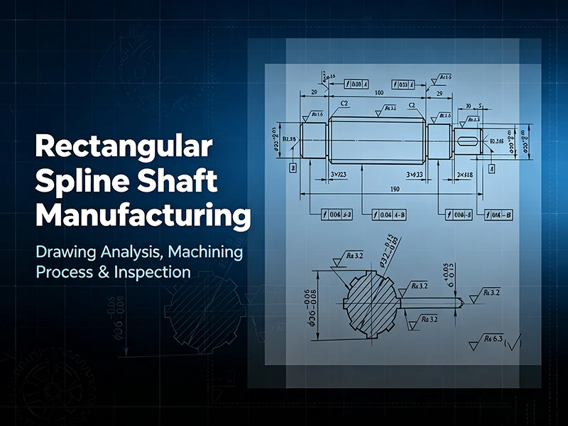
An incomplete gear drawing package is the single most common reason custom gear quotes take two weeks instead of two days.
At Hansheng Automation, we specialize in custom precision gears — spur, helical, bevel, gear shafts, and more — with over a decade of manufacturing experience serving robotics, automation, and industrial drive customers across the US, UK, and Canada. With processes ranging from gear skiving and hobbing to shaping and broaching, and a manufacturing capability down to module 0.1 and up to ISO/GB Grade 5 accuracy, we quote a wide range of gear geometries every week.
What slows things down is almost never the part itself. It’s the drawing package.
Missing a gear data table, writing “alloy steel” without a heat treatment spec, or specifying “precision grade” without referencing AGMA or ISO — each of these forces a back-and-forth that pushes your quote timeline from 48 hours to one weeks or more. This aritcle covers exactly what to include so your RFQ comes back fast, accurate, and ready to move forward.
The Complete Gear Drawing Package Checklist
A complete RFQ package for custom precision gears has two components: the right files, and the right technical data. Missing either one forces your supplier to make assumptions — and assumptions get priced as risk.
Files to Include
| File | Format | Notes |
|---|---|---|
| 2D Engineering Drawing | Must include all dimensions, tolerances, surface finish callouts, and a Gear Data Table. | |
| 3D CAD Model | STEP (.stp) | Required for machining verification; STL is not acceptable for precision gear work. |
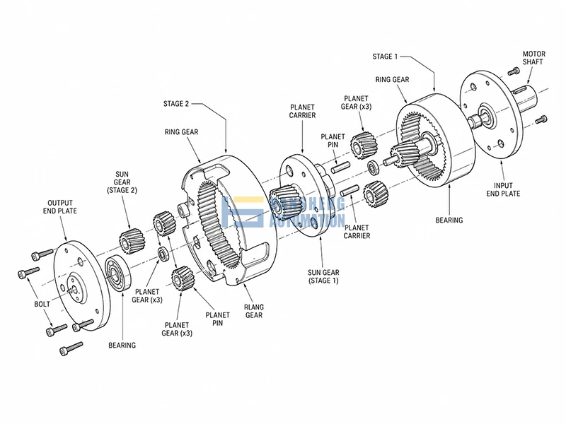
| Assembly Drawing | PDF (if applicable) | Shows how the gear interfaces with mating components — critical for planetary gear sets. |
Gear Data Table: Required Parameters
This is the section most drawings are missing. A gear data table is not a general parts list — it defines the tooth geometry your supplier needs to select tooling, verify mesh, and quote accurately.
| Parameter | What to Specify |
|---|---|
| Module (m) | Use metric module for ISO/DIN drawings; diametral pitch (DP) for AGMA/imperial. Do not leave this to be reverse-engineered from the 3D model. |
| Number of Teeth (z) | State for each gear in the system. For planetary sets, sun / planet / ring tooth counts must all be included. |
| Pressure Angle (α) | Standard is 20°. If your application requires a different value, state it explicitly with the reason. |
| Helix Angle (β) + Hand | Required for helical gears. Left-hand or right-hand must be specified — wrong hand means the assembly won’t work. |
| Accuracy Grade | Reference a standard: ISO 1328 Grade 5-7 for most precision applications; AGMA Q10-12 for North American drawings. “Precision” alone means nothing to a supplier. |
| Material + Heat Treatment | Specify alloy grade (e.g. 20CrMnTi, 9310 Steel) plus heat treatment type, case depth, and target hardness range. See Section 2 for why this matters. |
| Surface Finish (Ra) | Call out Ra separately for tooth flanks, bore, and face. Tooth flank Ra directly affects noise and service life. |
| Bore Tolerances / Fit | Use standard fit codes (e.g. H7, K6). A dimension without a tolerance class forces the supplier to assume — usually not in your favor. |

Why Each Item Matters: A Planetary Gear Example
Here’s a scenario we see regularly: a robotics engineer sourcing planetary gears for a humanoid robot joint actuator.
The application is demanding — compact envelope, high torque density, low backlash, and expected to survive thousands of hours of dynamic load cycling. The stakes for getting the gear specs wrong are high.
Three Drawing Gaps That Delay Quotes (and Cost More)
No Gear Data Table — “Just use the STEP file”
A 3D model defines geometry. It does not define tooth accuracy, tooling class, or inspection criteria. For a planetary gear set, the supplier needs to verify that sun, planet, and ring gear tooth counts satisfy the assembly condition, and that the chosen module and pressure angle are manufacturable with available tooling. Without a gear data table, a supplier cannot quote with confidence — they can only quote with contingency margin built in.
Material listed as “alloy steel, heat treated”
For robot joint gears running under continuous cyclic load, material selection is not interchangeable. A common specification for this application would be 20CrMnTi with case carburizing, effective case depth 0.5–0.8mm, and surface hardness HRC 58–62. Compared to a standard through-hardened steel, this process requires different pre-machining stock allowance, a post-heat-treatment grinding step, and additional inspection.
Accuracy grade written as “precision” or left blank
For a robot joint actuator, most engineers target ISO 1328 Grade 5–6 on the tooth flanks — tight enough for low noise and minimal transmission error under load, but achievable with gear grinding rather than requiring exotic finishing processes. Leaving the accuracy grade unspecified means the supplier chooses for you. That might mean Grade 8 (under-spec, noisy) or Grade 4 (over-spec, expensive and slow). Neither outcome is what you want.
What a Complete Drawing Package Enables
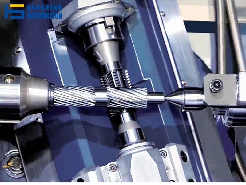
When the drawing package is complete — correct gear data table, full material and heat treatment callout, and a referenced accuracy grade — a supplier with the right equipment can commit to a quote within 48 hours. Processes like gear skiving (well-suited for internal gears in planetary sets) and gear hobbing (efficient for external spur and helical gears) are selected based on the accuracy grade and geometry specified in the drawing. Without that information, process planning cannot begin.
A Quick Note on Standards: AGMA vs ISO
If you’re sourcing from North America or Europe, the accuracy standard you reference on your drawing matters — not because one is better, but because suppliers tool and inspect to a specific system.
| AGMA | ISO 1328 / DIN 3962 | |
|---|---|---|
| Common in | US, Canada | UK, Europe |
| Grade range | Q3 – Q15 (higher = more precise) | Grade 12 – 3 (lower = more precise) |
| Typical robot joint spec | Q10 – Q12 | Grade 5 – 6 |
| On your drawing, write | "AGMA Q11 per AGMA 2000" |
"ISO 1328 Grade 6" |
Both standards are accepted in our quoting process. If your drawing references AGMA and you’re sourcing outside North America — or vice versa — note it explicitly. A one-line callout removes any ambiguity and prevents the supplier from defaulting to a lower grade.
One practical tip: If you’re unsure which grade to specify for a robot joint application, ISO Grade 5–6 is a reasonable starting point for tooth flank accuracy. Your supplier can advise on whether that’s achievable within your target cost and lead time before production begins.
Ready to Submit Your Gear RFQ?
If your drawing package covers the items in this guide, we can typically return a quote within 48 hours.
Not sure if your package is complete? Send it to us anyway. We review every submission and will flag any missing information before quoting — no charge for the review.
We regularly manufacture precision planetary gears, helical gears, spur gears, and gear shafts for robotics and automation customers in the US, UK, and Canada, with manufacturing capability from module 0.1 to 5.0, tip diameter up to 300mm, and accuracy to ISO/GB Grade 5.
FAQ
You can submit an inquiry without a finalized drawing, but the quote will be an estimate rather than a firm price. To return an accurate quote — covering material, process selection, tooling, and lead time — we need at minimum a gear data table with the key tooth parameters and a material specification.
With a complete drawing package, our standard quote turnaround is 48 hours. Incomplete submissions — missing gear data table, unspecified heat treatment, or no accuracy grade — typically require one or more rounds of clarification, which can push that out to 1 weeks. For planetary gear sets or multi-part assemblies, assembly drawings also help us quote faster and more accurately. The drawing package quality is the single biggest factor in quote speed.
Not necessarily — and it almost always means higher cost and longer lead time. Over-specifying accuracy grade is one of the most common mistakes in gear RFQs. For most robot joint and automation applications, ISO 1328 Grade 5–6 covers tooth flank accuracy requirements without requiring exotic finishing processes. Going to Grade 4 or tighter adds grinding time, inspection complexity, and cost — often without a measurable performance benefit in the actual application. Specify the grade that matches your functional requirement, not the tightest grade your supplier can achieve.
MOQ depends on complexity, module size, and tooling. Standard modules (m0.5–m3.0) allow small prototype batches. Custom modules may need dedicated tooling. We handle both prototypes and production – please provide prototype, pilot, and annual volumes in your RFQ.
Yes. We produce internal ring gears via gear shaping or skiving. Skiving achieves higher accuracy (ISO 5–7) and works well for compact designs with limited axial clearance. Shaping is more flexible for various geometries. Process selection is based on your drawing (module, tooth count, bore, accuracy).