Cylindrical Gear Manufacturing: A Complete Engineering Guide from Gear Blank to Final Inspection
Blog 2026-08-12
Cylindrical gear manufacturing requires more than accurate tooth cutting. Gear blank preparation, datum selection, heat treatment, finishing, and inspection each affect the final accuracy and performance of the part. This article examines the manufacturing process from a practical engineering perspective, based on real production practices.
While this article might be a bit dry, it provides a highly comprehensive overview. If you’d like to learn how we machine specific cylindrical gears, please check out our previous blog post. For more information on what we can do, feel free to visit our Gear Machining Capabilities page.
Understanding Cylindrical Gear Structures Before Machining
Part geometry strongly influences the machining sequence because different structures require different fixturing, datum access, and tool approach strategies.
Single and Multi-Gear Cylindrical Parts
Tubular or sleeve-type gears generally have L/d > 1. Bores may be smooth, keyed, or splined. Because the elongated blank has lower radial rigidity, the bore often needs to be established as a stable reference before external machining.
Disc Gears and Ring Gears
Disc and ring gears generally have L/d < 1 and may include a hub with a smooth or splined bore. Their shorter geometry allows a two-setup approach in many cases: establish one rough reference, machine the opposite face and bore, then reverse the part to complete the remaining features.
Shaft Gears
Shaft gears are stepped shafts with one or more integral gear sections. Center holes can establish a common rotational axis for turning and subsequent gear operations.
Gear structure is therefore the starting point for selecting the blank-machining route and the functional datum.
What Technical Requirements Must Be Controlled in Cylindrical Gear Manufacturing?
Before machining begins, review the drawing as a complete manufacturing document. Three groups directly influence the route: dimensional and positional tolerances, surface roughness requirements, and heat-treatment requirements.
Dimensional and Positional Tolerances
Dimensional and positional tolerances define which features must be established and protected through the process. Pay particular attention to bore, journal, face, and runout requirements.
Positional errors should be verified during blank machining, before tooth generation begins, because the cutting operation follows the established locating axis.
Surface Roughness Requirements
Surface roughness is part of the gear blank specification. Where a bore or face is used as a locating surface, its finish affects seating and measurement repeatability, so the specified Ra value should be achieved before that feature becomes the primary reference.
Heat Treatment Requirements
Material and heat-treatment requirements must be considered before the process route is fixed. They affect machining sequence, finishing allowance, tool selection, and the amount of material available for post-treatment finishing.
Treat heat treatment as a process-routing constraint, not a footnote. The detailed material and thermal-cycle choices are addressed later in the heat-treatment section.
Review these three groups before planning the operation. The drawing, rather than the tooth profile alone, determines the manufacturing route and inspection requirements.
How We Select Machining Datums for Cylindrical Gear Parts
Once a part is located from an unsuitable surface, subsequent operations may inherit the resulting geometric error. Establish the datum strategy before the first machining setup.
Design Datum, Assembly Datum, and Measurement Datum
The rule is straightforward: the machining datum should be as consistent as possible with the design datum, assembly datum, and measurement datum. When these four align, the part holds its geometry across every operation. When they diverge, stack-up errors compound through the process.
This alignment follows a logical chain:
Design Datum → Manufacturing Datum → Assembly Datum → Inspection Datum
The design datum is defined on the engineering drawing. The manufacturing datum is the surface or feature used for machining support; the assembly datum locates the gear in service; the inspection datum is the reference used for verification. The goal is to keep these references consistent or directly related.
When the bore serves as the locating datum for machining and inspection, the same functional axis can be verified throughout the process, reducing reference-change errors.
Datum Strategy for Tubular and Multi-Gear Parts
For tubular gears (single or multi-gear sleeves with L/d > 1), the bore is the master datum. End faces serve as secondary locating surfaces for axial positioning. We follow a fixed sequence:
- Finish the bore first: rough and finish the bore to IT7 before any external turning. The bore must hold its tolerance and surface finish because every subsequent operation references it.
- Mount the blank using the finished bore as the locating reference for subsequent external machining.
- Machine all external features in one setup: with the bore as the master, cut the O.D., both end faces, and any relief grooves. For multi-gear sleeves, we also check runout between gear positions against the bore axis during this setup.
Bore-first machining provides a repeatable internal reference for subsequent operations on elongated blanks.
Datum Strategy for Disc Gears and Ring Gears
Disc and ring gears (L/d < 1) use a two-setup approach because the short, stiff blank allows flipping without losing geometric integrity:
- First setup: use the raw O.D. and one end face as rough locating datums. Machine the opposite end face, the bore, and any external grooves. The bore may be roughed or finished at this stage depending on the heat treatment cycle.
- Second setup: flip the blank. Locate from the machined bore (or the finished face if the bore is not yet final) and complete the remaining end face, O.D. surfaces, and other features.
For disc gears with a hub, verify face runout relative to the bore axis before the second setup is established.
Datum Strategy for Shaft Gears
Shaft gears (stepped shafts with integral gear sections) locate from center holes drilled in both end faces. The center holes establish a single rotational axis that serves as the locating datum for all turning, grinding, and gear cutting operations.
The sequence prioritizes the center holes from the start:
- Machine both end faces: square and flat faces provide the reference for drilling accurate center holes.
- Drill the center holes. These become the primary locating reference for the subsequent turning and gear operations.
- Turn between centers: rough and finish all O.D. surfaces, including gear blank diameters, bearing journals, and seal grooves, with the workpiece driven by a lathe dog or face driver.
- Cut gear teeth: hobbing or shaping is performed between the same centers, ensuring the tooth pitch cylinder remains concentric with the shaft axis.
Center-hole locating allows the part to be removed and re-mounted between compatible operations while retaining the same rotational reference.
Three part structures, three datum strategies:
| Part Type | L/d Ratio | Master Datum | Secondary Datum | Critical Check |
|---|---|---|---|---|
| Tubular / multi-gear | >1 | Bore (IT7) | End face | Runout between gear positions |
| Disc / ring gear | <1 | Bore + face (two-setup) | Raw O.D. | Face runout relative to bore |
| Shaft gear | variable | Center holes | End faces | Concentricity across journals |
The datum strategy determines whether geometry can be carried consistently across multiple setups. The key principle is to establish the functional reference early and preserve it through the process.
Cylindrical Gear Blank Machining: How the Foundation of Gear Accuracy Is Established
What happens before the teeth are cut? Gear blank machining establishes the datums, key dimensions, and stock condition that the tooth-cutting operation relies on.
General Cylindrical Gear Manufacturing Route
A typical manufacturing route can be summarized as:
Blank Manufacturing → Blank Heat Treatment → Gear Blank Machining → Rough Tooth Cutting → Gear Heat Treatment → Tooth Finishing → Inspection
Here is what each stage actually delivers:
The position of heat treatment depends on the selected material and treatment. Case-hardened gears generally use rough tooth cutting before treatment and final finishing afterward.
Machining Route for Shaft Gear Blanks
Shaft gear blank preparation follows a three-step sequence:
End Face Machining → Center Hole Drilling → Rough and Finish Turning
1.Machine both end faces: square, flat faces provide the reference surfaces for accurate center hole drilling. Any taper or waviness on the end faces transfers directly to the center hole position.
2.The center hole is a primary locating feature for shaft gears. It establishes the rotational reference for rough and finish turning and for compatible subsequent operations.
3.Rough and finish turn between centers: with the part driven by a lathe dog or face driver, we turn all O.D. surfaces: gear blank diameters, bearing journals, seal grooves, and shoulders. Roughing removes the bulk of stock; finishing brings the surfaces that serve as inspection and assembly datums to final dimension. Gear blank diameters receive their tooth-cutting stock at this stage.
Three Machining Routes for Disc Gear Blanks
Disc and ring gears (L/d < 1) can use different blank-preparation routes depending on bore geometry, production volume, equipment, and tolerance requirements.
Route 1 – Broaching-Based Sequence
Drilling/Reaming → Broaching → Bore-Based Positioning → Rough and Finish O.D. and End Faces
This route is suited to production where a dedicated broaching operation is justified, particularly for splined or keyed bores.
- Drill and ream the bore to prepare for broaching.
- Broach the bore to the required geometry, such as a round, keyway, or spline bore, when that route is specified.
- Locate the blank from the finished bore for subsequent external machining.
- Rough and finish the O.D. and both end faces in a single setup.
The main advantage is that the finished bore becomes the locating reference before external machining. The trade-off is the cost and geometry-specific nature of broaching tooling.
Route 2 – Conventional Turning Sequence
Turn Bore, End Face, and Part of O.D. → Finish Bore → Turn Second End Face and Remaining O.D.
This route can suit medium batches and bores that do not require broaching:
- First setup – chuck on the raw O.D. and locate against one face. Turn the bore, face the first end face, and turn a portion of the O.D.
- Finish bore – if bore tolerance is IT7 or tighter, perform a finish boring operation to bring the bore to final dimension.
- Second setup – locate from the finished bore (or the turned O.D.) and complete the remaining end face and O.D. surfaces.
The sequence ensures the bore reaches its final tolerance before the second setup locks the part for O.D. completion.
Route 3 – CNC Turning with Flip
CNC Turn Bore, End Face, and Part of O.D. → Reverse → Complete Second Side
This is the modern, flexible route for small to medium batches:
- Chuck the raw blank on its O.D. CNC turn the bore, first end face, and the accessible O.D. surfaces.
- Reverse the part. Locate from the machined features (bore or turned O.D.) and complete the remaining end face and O.D. surfaces in the second setup.
CNC turning combines the accessible bore, face, and O.D. operations into two setups, providing a flexible option for small to medium batches.
Gear Blank Type vs. Datum Strategy
For quick reference on the shop floor or in procurement review, here is how each blank type maps to its primary datum and machining logic:
| Gear Blank Type | Locating Features (Datums) | Typical Machining Sequence |
|---|---|---|
| Shaft gear | Center holes (primary); end faces (secondary) | Face both ends → drill center holes → rough and finish turn between centers |
| Disc gear | Bore and finished face (bore locates O.D.; face sets axial position) |
Machine bore and first face → locate from bore → reverse and complete second face and O.D. |
| Ring gear | Bore, face, and O.D. (rough locating from O.D./face; finish locating from bore after first setup) |
Rough locate from O.D. and one face → machine opposite face and bore → flip → locate from bore to finish remaining surfaces |
Material Selection for Cylindrical Gear Manufacturing
Material selection should match the gear service condition and the required heat-treatment route. The material choice affects strength, wear resistance, toughness, machinability, and dimensional stability.
What Determines Cylindrical Gear Material Selection?
Seven factors govern gear material selection decisions:
- Load magnitude and fatigue limit: higher loads demand higher core strength and endurance limits.
- Bending strength and wear resistance: the tooth root acts as a cantilever beam; the flank sees repeated contact stress.
- Impact toughness: shock loads require sufficient core toughness to prevent tooth fracture.
- Transmission accuracy: tighter accuracy classes require materials with stable heat-treatment behavior and minimal distortion.
- Heat-treatment suitability: the selected grade must respond predictably to the specified thermal cycle (carburizing, nitriding, induction, or through-hardening).
Common Materials Used for Cylindrical Gears
The grades below should be selected according to load, wear, impact, accuracy, and heat-treatment requirements:
| Material Family | Typical Grades | Selection Consideration |
|---|---|---|
| Low-carbon alloy steel | 20Cr, 20CrMo, 20CrMnMo, 20CrMnTi | Suitable where carburizing is required for a hard case and tough core. |
| Medium-carbon alloy steel | 40Cr, 42SiMn | Suitable for applications using quench-and-temper and/or induction hardening. |
| Medium-carbon structural steel | 45 | Common choice for lower-cost, lower-load gear applications and selected induction-hardened applications. |
| Medium-carbon manganese steel | 50Mn2 | Used for large gears in applications where the specified strength and heat-treatment route are appropriate. |
Select the material only after defining the duty cycle and the required heat-treatment condition. The specific material-treatment combinations are detailed in the next section.
Heat Treatment in Cylindrical Gear Manufacturing: Material, Process and Hardness
Heat treatment should be selected from the required service condition, material grade, hardness target, and dimensional requirements. The source material provides several representative combinations.
Carburizing for High-Speed and Impact Loads
For high-speed, high-load or impact applications, the source material specifies carburizing routes that produce a hard surface with a tougher core.
For gears with module < 5 mm operating under these conditions, the standard material-process combination is:
- Materials – 20Cr, 20CrMn
- Process – carburize at 900–950°C, then quench directly or reheat to 800–820°C for oil quenching
- Temper – 180–200°C
- Final hardness – 58–63 HRC
To small-module gears, case depth should be matched to tooth geometry and the specified heat-treatment requirement.
Carburizing for Automotive and Tractor Transmission Gears
Heavy-duty drivetrain gears demand deeper case hardness and higher core strength. The automotive and tractor sector runs a well-established set of gear heat treatment combinations:
| Material | Process | Final Hardness | Application |
|---|---|---|---|
| 20CrMnTi | Carburize + quench + temper | 58–63 HRC |
Transmission gears, differential gears |
| 20CrMo | Carburize + quench + temper | 58–63 HRC |
Drive axle gears, planetary gears |
| 20CrMnMo | Carburize + quench + temper | 58–63 HRC |
Heavy-duty drive gears, shaft gears |
Q&T and Induction Hardening for 40Cr and 42SiMn
40Cr and 42SiMn are shown in the source material with quench-and-temper treatment followed by high-frequency induction hardening and tempering.
The sequence is consistent across both grades:
Q&T → High-frequency induction heating → Emulsion or water quench → Low-temperature temper
The hardness range depends on the tempering temperature selected after induction:
| Material | Prior Treatment | Induction Cycle | Temper | Final Hardness |
|---|---|---|---|---|
| 40Cr, 42SiMn | Q&T (840–860°C oil quench, 600–650°C temper) |
860–880°C high-frequency induction |
280–320°C | 45–50 HRC |
| 40Cr, 42SiMn | Same prior treatment | 860–880°C high-frequency induction |
180–200°C | 50–55 HRC |
Heat Treatment Selection Follows Working Conditions
The selection logic can be summarized as:
Load → Speed → Impact → Material → Heat Treatment → Hardness
| Working Condition | Recommended Route | Typical Materials | Final Hardness |
|---|---|---|---|
| High speed + high impact + high cycle | Carburize + quench + temper | 20CrMnTi, 20CrMo, 20CrMnMo | 58–63 HRC |
| Medium speed + moderate load | Q&T + induction harden + temper | 40Cr, 42SiMn | 45–55 HRC |
| Low speed + low load | Normalize or through-harden | 45, 50Mn2 |
156–241 HBW
or
45–50 HRC
|
Do not select the heat-treatment route from hardness alone. Match the material, working condition, hardness requirement, and dimensional needs before fixing the process route.
Gear Cutting, Finishing and the Final Accuracy Chain
Once the gear blank is ready, tooth cutting generates the gear geometry and finishing brings the teeth to the specified final condition.
Rough Gear Machining
Rough hobbing, shaping, or milling generates the tooth form while leaving sufficient stock for the specified post-treatment finishing operation. Determine the exact allowance from the drawing, material, heat-treatment route, and finishing method.
Heat Treatment Before Final Tooth Finishing
For case-hardened gears, a common sequence is:
Rough Cutting → Heat Treatment → Final Finishing
After case hardening, final tooth finishing should be selected
Why Gear Finishing Must Reference Stable Functional Datums
Finishing removes material. It does not correct misalignment. The datums used for final tooth finishing must match those used for blank machining. Otherwise, distortion from hardening shifts the axis and the teeth grind off-location.
After heat treatment, restore the functional locating feature as needed before final tooth finishing. Where heat treatment changes the locating geometry, restore the relevant datum before final tooth finishing so that the tooth geometry is generated from the intended functional reference.
Quality Control in Cylindrical Gear Manufacturing
Final inspection should verify that the features controlled during machining still meet the drawing after finishing and heat treatment.
Datum Surface Accuracy
Verify the final condition of the locating and measuring features that control assembly and inspection.
- Bore: check diameter to the specified IT grade (typically IT7 for master datums). Plug gauges or bore micrometers confirm size; roundness and taper must fall within tolerance.
- End face: verify flatness and perpendicularity to the bore axis. Face runout at the gear rim should not exceed the drawing limit.
- Center holes (shaft gears): inspect for concentricity, taper, and surface condition. Worn or off-center center holes invalidate all subsequent shaft measurements.
- Journal O.D.: check diameter and roundness for shaft gears that locate on bearing surfaces during assembly.
Dimensional and Positional Tolerances
Check all dimensional and positional requirements against the drawing, with particular attention to the bore, journal, face, and runout features that define assembly or measurement references.
- Datum surface dimensions: bore I.D., shaft O.D., face widths, and hub diameters against specified IT grades.
- Positional tolerances: concentricity between the bore and pitch circle, perpendicularity of end faces to the bore, and runout across multiple gear sections on a shaft.
If the blank’s locating surfaces fail these checks, the tooth profile is irrelevant. The gear cannot locate correctly in the housing..
Surface Roughness
Verify the specified surface roughness on locating faces, bores, shoulders, and tooth flanks where applicable. The inspection method should match the feature and the drawing requirement.
Heat Treatment and Hardness Verification
Hardness testing verifies the specified heat-treatment condition. Use the measurement scale and test location required by the drawing or heat-treatment specification.
Verify case depth where the drawing or heat-treatment specification requires it.
Final Inspection
The final inspection should compare the finished gear against the complete drawing and the specified gear-accuracy requirements.
- Tooth profile – involute form errors
- Tooth lead – helix angle deviation
- Pitch accuracy – adjacent pitch error and total cumulative pitch error
- Runout – radial and axial runout relative to the locating datum
- Surface finish on tooth flanks – Ra or Rz as specified
Where the drawing calls for AGMA, DIN, ISO, or GB/T requirements, the final acceptance decision should be based on the specified standard and tolerance class.
- Actual measurement values for each inspected feature
- Inspection method or equipment used for each requirement, as applicable
- Pass/fail status for each requirement
For procurement acceptance, the inspection report should record the actual measurements required by the drawing and clearly identify pass/fail status.
Common Cylindrical Gear Manufacturing Risks and How to Control Them
The recurring process risks can be grouped into four areas: datum selection, blank preparation, heat-treatment changes, and inspection-reference mismatch.
Incorrect or Unstable Datum Selection
An incorrect locating surface can propagate geometric error through subsequent operations.
Control this by preserving the established functional datum through the relevant setups.
Inadequate Gear Blank Preparation
The gear blank must meet the specified geometric condition before tooth cutting begins.
Verify the blank geometry before tooth cutting rather than assuming the preceding turning operation is sufficient.
Heat Treatment-Related Dimensional Changes
Heat treatment can change dimensions and locating geometry, so the process route should include allowance for post-treatment verification and, where required, datum restoration.
Control this by planning finishing stock and post-treatment verification from the specified thermal cycle.
Inconsistent Inspection References
When the inspection reference differs from the machining reference, the measured geometry may not represent the same functional relationship.
Control this by keeping the inspection reference consistent with the established manufacturing and functional datums whenever the drawing permits.
| Risk | Source | Control Measure |
|---|---|---|
| Incorrect datum selection | Misaligned design vs. manufacturing references | Apply consistency rule:design = manufacturing = assembly = measurement |
| Poor blank preparation | Bore out-of-round, face not square, center holes off-axis | Verify blank geometry before loading hobber |
| Heat-treatment distortion | Quenching warps bores, faces, and center holes | Leave finishing stock; re-grind datums post-hardening |
| Inconsistent inspection references | Fixture references differ from machining references | Maintain same datum across all setups and checks |
Cylindrical Gear Manufacturing Process: Complete Workflow
What Buyers Should Provide When Ordering Custom Cylindrical Gears
What technical information should a buyer provide so a manufacturer can evaluate a cylindrical gear RFQ accurately?
Part Drawing
The drawing is the primary technical document. It should include:
- Dimensions: all gear blank O.D.s, bore sizes, face widths, hub dimensions, and overall length.
- Tolerances: IT grades for bore, O.D., and face surfaces; positional tolerances including concentricity, perpendicularity, and runout.
- Datum references: clearly identified locating, measuring, and assembly datums. The manufacturer must know which surfaces control the process.
- Surface roughness: Ra or Rz values for locating faces, bore surfaces, and tooth flanks.
- Gear geometry: module or diametral pitch, number of teeth, pressure angle, helix angle, profile shift, and tooth thickness, where applicable.
- Accuracy grade: AGMA, DIN, ISO, or GB/T quality class specified for the finished gear.
Clear datum references are essential for process planning because the manufacturer must know which features control machining and inspection.
Material and Heat Treatment
Material selection drives the entire manufacturing sequence. Provide:
- Material grade – full standard designation (e.g., 20CrMnTi, 40Cr, 45, 42SiMn).
- Heat treatment specification – carburizing, nitriding, induction hardening, through-hardening, or quench-and-temper.
- Hardness requirement – target HRC or HBW range and any case depth requirements.
- Pre-treatment condition – forged, cast, or bar stock; normalized or annealed if applicable.
If the material is non-standard, provide the applicable material standard or an approved equivalent for cross-reference.
Quantity and Production Requirements
Production volume determines tooling amortization, process selection, and lead time. Include:
- Prototype quantity – sample parts for validation before full production.
- Batch quantity – number of pieces per production run.
- Annual demand – total expected volume over 12 months.
- Packaging requirements – anti-rust coating, individual wrapping, bulk packaging, or palletized shipment.
- Delivery expectations – target lead time for first article approval and ongoing production shipments.
For custom cylindrical gears, evaluate the required tooling and fixture strategy together with the production volume and geometry.
Quick RFQ Checklist
| Required Information | Why the Manufacturer Needs It |
|---|---|
| ✔ Complete part drawing with datums | Determines blank prep sequence, fixture design, and inspection method |
| ✔ Material grade and heat treatment | Drives cutter selection, stock allocation, and thermal cycle planning |
| ✔ Hardness and case depth | Defines finishing operation (grinding vs. hard hobbing) and grinding wheel selection |
| ✔ Prototype, batch, and annual volumes | Guides tooling investment, process selection, and quoting structure |
| ✔ Packaging and delivery | Determines shipping method and inventory planning |
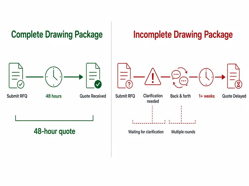
Complete RFQs make it easier to evaluate the machining route, tooling needs, heat treatment, and inspection requirements before quotation.
From Drawing Review to Custom Cylindrical Gear Production
Once the drawing and technical requirements are received, the supplier-side engineering review can follow this sequence:
Drawing → Engineering Review → Process Planning → Material Confirmation → Machining → Heat Treatment → Inspection → Delivery
Drawing Review: Verify dimensions, tolerances, datums, surface roughness, gear geometry, and accuracy grade. Missing information stops the process.
Process Planning: Identify part structure (tubular, disc, ring, or shaft) and assign the corresponding datum strategy. L/d ratio determines the primary locating feature.
Material Confirmation: Check material grade and heat treatment specification against stock availability. Non-standard grades affect lead time.
Machining Route: Select blank preparation route based on batch size, bore geometry, and tolerance. Allocate stock for heat-treatment distortion.
Heat Treatment: Confirm furnace cycle against hardness and case depth requirements. Plan post-treatment machining allowances.
Inspection: Define inspection methods for bore, face, center holes, tooth profile, pitch, and surface finish. Measurement datum must match manufacturing datum.
Delivery: Schedule production against customer timeline. Factor in tooling, heat treatment, and inspection slots.
This sequence connects drawing review to process planning, production, inspection, and delivery.Submit your drawing for a process review. The review should cover structure, datum strategy, blank routing, material, heat treatment, and inspection requirements before production is scheduled.
FAQ
Cylindrical gear manufacturing covers the production chain from gear blank preparation and tooth cutting through heat treatment, finishing, and final inspection.
Common grades in the source material include 20Cr, 20CrMo, 20CrMnMo, 20CrMnTi, 40Cr, 42SiMn, 45, and 50Mn2. The final choice depends on load, wear, impact, accuracy, and heat-treatment requirements.
Use a datum strategy that keeps the manufacturing, measurement, assembly, and design references consistent or directly related.
Representative routes in the source material include carburizing + quenching + tempering for 20Cr-family transmission gears, Q&T + induction hardening for 40Cr/42SiMn, and normalizing or other through-hardening routes for selected 45/50Mn2 applications. The required hardness depends on the specified duty and heat-treatment cycle.
Yes. A complete drawing with dimensions, tolerances, datums, roughness, gear geometry, and accuracy grade is the standard starting point. We review the drawing, plan the machining route, confirm material and heat treatment, and quote based on specifications and batch volumes. Submit your drawing for a process review to receive a clear manufacturing plan and firm quote.