Custom Spur Gear Machining Case Study: Web-Type Gear from ZG270-500 Cast Steel
Blog 2026-07-25
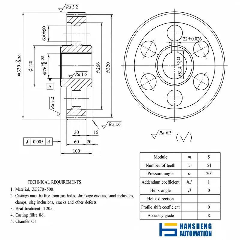
This case study details the medium-batch manufacturing of ZG270-500 cast steel (equivalent to ASTM A27 Grade 70-36 / DIN 1681 GS-52) web-type spur gears, showcasing our comprehensive approach to custom spur gear machining. The full process route covers: Casting → Annealing → Rough Turning → Quenching & Tempering (Q&T) → Finish Turning → Hobbing → Keyway Broaching → Final Inspection. Final bore achieved φ76(+0.03/0) mm with Ra ≤ 1.6 µm surface finish, and tooth accuracy meeting ISO 8 grade.
Disclaimer: This is a real-world manufacturing case from Hansheng Automation. Certain proprietary features and exact dimensions have been modified for intellectual property protection.
What Is a Web‑Type Spur Gear?
A web-type spur gear features a thin annular web—rather than a solid disc—connecting the central hub to the outer tooth rim. This construction significantly reduces component weight and rotational inertia while retaining sufficient torsional rigidity for most industrial drive applications.
Common applications include material handling gearboxes, wind turbine drives, and heavy-duty reducers, where reducing rotational inertia enhances dynamic performance without sacrificing load capacity. The web may incorporate lightening holes or a curved profile depending on stress requirements, but the basic geometry remains a plain radial web connecting hub and rim.
ZG270-500 Spur Gear Specifications & Key Machining Challenges
| Parameter | Value |
|---|---|
| Component | Web type spur gear |
| Blank | ZG270-500 (ASTM A27 70-36 / DIN GS-52 Equivalent) |
| Outer diameter (finished) | φ330(0/-0.20) mm |
| Overall length | 106 mm |
| Face width (after finish turning) | 60 mm |
| Bore (finished) | φ76(+0.03/0) mm |
| Bore surface roughness | Ra ≤ 1.6 μm |
| Tooth accuracy target | ISO 8 |
Three Core Machining Challenges
Tight Bore Tolerance & Surface Finish
Achieving aφ76 (+0.03/0) mm bore with an Ra 1.6μm finish leaves no margin for error (0.03 mm tolerance band). This mandates strict separation of rough and finish boring, along with precise thermal and tool-wear control during final passes.
Residual Stress in Cast Blanks
Machining raw ZG270-500 castings without stress relief causes severe component distortion—specifically bore ovality and radial runout once unclamped. Stress-relief heat treatment before finish machining is critical to stabilize the microstructure.
Datum Consistency & Concentricity
When flipping the part for second-side machining, the finished bore serves as the primary locating datum to preserve coaxiality across the bore, pitch circle, and outer diameter. Any datum transfer error directly introduces gear tooth runout and premature wear.
Heat Treatment in Custom Spur Gear Machining for ZG270-500 Cast Steel
Pre-Machining Annealing
As‑cast ZG270‑500 contains dendritic segregation and locked‑in thermal stresses from uneven solidification. Machining unannealed castings causes rapid tool wear from uneven hardness and triggers part distortion as residual stresses are released during cutting.
We perform full annealing in a box‑type furnace—uniform heating to the appropriate austenitising range, followed by slow controlled cooling through the critical transformation zone. The objective is to homogenise the microstructure and bring hardness down to a consistent, machinable level.
We once processed a foundry batch with inadequate annealing. Post-rough turning bore ovality reached 0.15 mm—five times our allowable finishing tolerance—forcing us to scrap the batch. Since then, incoming hardness and microstructural verification has been an uncompromised Quality Gate.
Quenching and Tempering (After Rough Turning)
Why Quenching & Tempering (Q&T) Follows Rough Turning:
Rough turning removes the as‑cast surface layer, decarburised zone, and most of the uneven stock. The remaining section thickness is more uniform, so the subsequent quench produces a more consistent martensitic transformation across the gear body. Tempering then follows to achieve the required balance of strength and toughness.
Hardness is locked to 190–220 HBW across every batch. We adjust tempering temperature to fine‑tune the final hardness, not the quenching stage, because quench response is primarily set by the steel chemistry and section size. Each batch is sampled and verified before release to finish machining.
Furnace Loading Precision: Gears are individually spaced inside the box furnace. Contact or overcrowding blocks heat circulation, resulting in localized soft spots that disrupt finishing tolerances and bore roundness. That creates inconsistent cutting conditions during finish turning and directly affects bore roundness. We check furnace loading patterns on every cycle.
Step-by-Step Custom Web-Type Spur Gear Machining Process
Phase 1: Rough Turning in Custom Spur Gear Production
The rough turning stage in custom spur gear production must account for cast blank variability and residual stress.
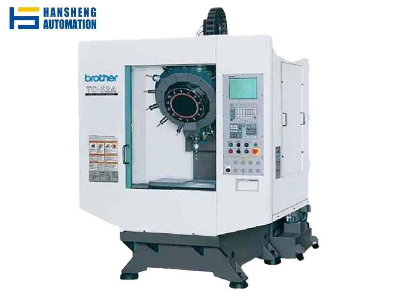
Equipment: Brother TC‑S2A CNC lathe or Taesin TXC‑T6 mill‑turn centre. Both offer high‑rigidity spindles capable of handling the interrupted cuts and variable stock removal typical of cast steel blanks.
First setup (one end):
- Three‑jaw self‑centring chuck grips the as‑cast O.D. (φ330 nominal). Runout is indicated and corrected to within 0.1 mm before clamping. Operations in sequence:
- Face the hub side to 38 mm from the web face.
- Face the tooth side to 18 mm from the web (this establishes the initial axial reference).
- Rough turn O.D. to φ335 mm, leaving ~2.5 mm per side for finish turning.
- Rough bore to φ71 mm, leaving ~2.5 mm per side.
Second setup (flip):
- Chuck on the previously turned O.D. (φ335). Face the opposite end to achieve overall length 106 mm. Rough the tooth width to 66 mm, leaving 6 mm total stock for finish turning (3 mm per face).
- Tooling: 45° approach turning tool for facing operations, 90° tool for O.D. turning. Both with CNMG inserts in grade suitable for cast steel (ISO P20–P30 range).
Quality check after rough turning:
Measure O.D. and bore diameters at multiple circumferential positions to verify uniform stock distribution. Uneven wall thickness indicates either chuck misalignment or casting eccentricity — both must be corrected before heat treatment, otherwise the subsequent Q&T stage will not have balanced section thickness, leading to distortion. Stock should be sufficient to clean up after tempering, with at least 1.5mm minimum remaining on the tightest side.
Phase 2: Post-Heat Treatment Precision Turning & Boring
For custom spur gear machining that meets ISO 8 and Ra1.6, the finish boring parameters must be tightly controlled.
Equipment: Brother TC‑S2A CNC lathe (spindle runout≤ 2μm, essential for achieving Ra1.6μm and the tight bore tolerance).
First setup (one end):
- Chuck on the O.D. (now tempered, hardness 190–220 HBW). Sequence:
- Finish face the hub side to 35 mm from web.
- Finish face the tooth side to 15 mm from web.
- Finish turn O.D. to final φ330(0/-0.20).
Critical Step–Finish Boring (φ71 mm to φ76 +0.03/0 mm):
- Cutting Speed: ~120 m/min (minimizes thermal drift and tool wear)
- Feed Rate: 0.10–0.12 mm/rev (ensures low theoretical roughness)
- Tool Nose Radius: 0.8 mm (optimal balance between surface finish and deflection control)
- Depth of Cut: 0.3 mm (maintains stable cutting action without boring bar deflection).
After boring, chamfer bore mouth and O.D. edges to C1.
Second setup (flip, locating on the bore):
- Second setup (flip, locating on the bore):
- Clamp on the finished O.D. (using soft jaws or a diaphragm chuck) and indicate the finished bore to establish runout within 0.01 mm. This ensures coaxiality between the bore, the pitch circle (to be hobbed later), and the O.D.
- Face the opposite hub side to bring overall hub length to 100 mm (final dimension).
- Face the tooth side to achieve the finished face width of 60 mm.
- Finish turn the remaining O.D. section to match the previously turned surface, then chamfer C1.
In‑process quality check:
Immediately after finish boring, measure bore diameter with an internal micrometer (or bore gauge) at three axial positions and two angular orientations (90°apart). Check surface roughness with a portable profilometer. The bore is the primary datum for subsequent gear cutting — any deviation here will directly affect tooth runout. We reject any bore that exceeds the tolerance or roughness limit before proceeding to hobbing.
Phase 3:CNC Gear Hobbing for Custom Spur Gears
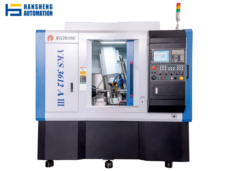
For this particular component–an external spur gear ofφ330 O.D.–we selected a large-capacity CNC hobbing machine with a maximum workable diameter of at least 400 mm. The teeth are cut in a single pass, avoiding the accumulated errors that would arise from a second setup. With the machine’s inherent accuracy and proper tool selection, ISO 8 tooth grade is consistently achieved without resorting to subsequent grinding or shaving.
Why Hobbing?
For standard external spur profiles in medium-batch runs, CNC hobbing provides the shortest cycle times and lowest per-part tooling costs while reliably maintaining ISO Grade 8 accuracy without secondary grinding.
Phase 4:Keyway Broaching & Deburring
Keyway broaching:
The bore keyway is cut on a Nachi broaching machine – Japanese‑built, with a rigid pull‑type design that maintains consistent tool alignment through the cut. Broaching is a single‑stroke operation once the tool and bushing are set, which gives excellent repeatability across the batch.
After broaching, every keyway is checked with a Go/No‑Go plug gauge for width. Symmetry relative to the bore centreline is verified using a keyway symmetry gauge or a height gauge on a surface plate – this step is often overlooked in general machining, but a symmetric keyway is critical for torque transmission without inducing bending stresses on the shaft. We reject any part where the keyway deviates beyond the tolerance band specified in the drawing.
Bench Deburring & Edge Chamfering:
All sharp edges — including bore edges, O.D. corners, tooth tips, and web transitions — are deburred at a dedicated bench station. Proper chamfering eliminates operator hazards during gearbox assembly and prevents edge-chipping during international transit. After deburring, parts are visually inspected for any remaining burrs or sharp spots before proceeding to final inspection.
Final Quality Inspection and Packaging Standards
CMM & Gear Inspection Protocol (100% Bore & Profile Testing)
All finished gears undergo a defined inspection sequence before release. The bore is the primary datum, so every part is checked there. Tooth geometry and hardness are verified on a sampling basis, with the sample size determined by batch quantity per standard statistical practice.
| Inspection Item | Measuring Equipment | Scope | Acceptance Criterion |
|---|---|---|---|
| Bore diameter φ76(+0.03/0) | Coordinate measuring machine (CMM) or air gauge | 100% | Within tolerance band; no taper or ovality exceeding 0.01 mm |
| Surface roughness Ra (bore) | Profilometer (on CMM or portable) | 100% (alongside bore check) | ≤ 1.6 μm |
| Tooth accuracy – base tangent length, radial runout, profile & lead | Gear inspection instrument (e.g. Klingelnberg or Gleason) | Sampling per batch (typically 5-10 pieces, or as agreed) | ISO 8 or better |
| Hardness | Portable hardness tester (e.g. Leeb) | Sampling, at least 2 pieces per batch | 190–220 HBW |
Notes:
- Bore measurement is performed at three axial positions (near each end and mid‑length) and at two angular orientations (90° apart) to capture any taper or lobing.
- If the bore diameter or roughness fails on any piece, that piece is segregated, and the cause is investigated. The preceding five pieces and following five pieces are also re‑inspected.
- Tooth inspection reports are generated for each sampled piece; these can be included with the shipment upon request.
- Hardness test locations are specified on the gear web (not on the teeth or bore) to avoid damaging functional surfaces.
Solvent Cleaning & VCI Anti-Rust Export Packaging
Cleaning
After final inspection, each gear is washed in a solvent‑based parts washer to remove cutting fluid, chips, and any handling contaminants. The bore and keyway are flushed separately to ensure no residue remains.
Rust prevention
Within two hours of cleaning, a rust‑preventive oil (grade consistent with long‑term storage and sea freight) is applied uniformly over all surfaces – bore, keyway, tooth flanks, and external faces. After oiling, each gear is individually wrapped in VCI (vapour corrosion inhibitor) paper, which adds an extra protective layer during transit.
Packaging
Wrapped gears are placed in corrugated cardboard boxes or wooden crates (depending on weight and shipping method). Each gear is separated from others by bubble wrap or foam padding, and fixed in place with inserts to prevent shifting or collision during handling. For multiple gears per box, dividers are used to avoid metal‑to‑metal contact.
Custom Spur Gear Manufacturing Services (OEM & ODM)
This case demonstrates our proven capability with ZG270‑500 cast steel web‑type spur gears – φ330 O.D., φ76(+0.03/0) bore, Ra 1.6 μm finish, ISO 8 tooth accuracy – processed entirely in‑house through annealing, rough turning, Q&T, finish turning, hobbing, broaching, and final inspection.
We offer comprehensive OEM gear manufacturing services backed by multi‑process gear cutting (hobbing, shaping, skiving), in‑house heat treatment, and full inspection equipment including CMM and gear testing instruments. Small to medium batches are accepted, and we work to customer prints for both OEM and ODM projects.
Send your drawing (CAD or PDF) for a feasibility review and a prompt quotation.
FAQ
ZG270-500 cast steel (comparable to international grades ASTM A27 Grade 70-36 and DIN GS-52) provides excellent strength, toughness, and wear resistance at a lower cost than forged steel. The main challenge lies in non-uniform as-cast microstructures and residual stresses that cause tool wear and part distortion. We resolve this through pre-machining annealing and post-roughing quenching & tempering (Q&T).
We separate rough and finish boring on high-precision CNC lathes with spindle runout below 2 μm. Finish boring uses strict parameters—cutting speed at ~120 m/min, feed rate at 0.10–0.12 mm/rev, a 0.8 mm nose radius tool, and a 0.3 mm depth of pass—to eliminate thermal expansion and tool bar deflection.
Yes. For standard medium-batch external spur gears, high-rigidity CNC hobbing machines consistently achieve ISO Grade 8 profile, lead, and runout tolerances in a single pass. This avoids costly secondary grinding or shaving, reducing both lead time and per-part tooling costs.
A web-type spur gear replaces a solid disc with a thin annular web, significantly reducing overall component weight and rotational inertia. This improves machine dynamic response and energy efficiency in gearboxes without compromising required torsional rigidity and load capacity.
Please provide 2D and 3D CAD drawings (PDF, STEP, or IGES) specifying tooth parameters (module, pressure angle, tooth count), material requirements (e.g., ZG270-500), heat treatment hardness specs, critical tolerances, surface finish requirements, and estimated batch quantities.