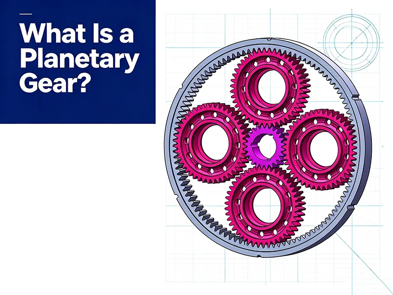
From CAD to Production: Stage 1 vs Stage 2 Ring Gear Tolerances in Compact Robotic Actuators
Blog 2026-06-11
Ring gear tolerances in two-stage planetary actuators are rarely specified correctly — most drawings assign the same tolerance class to both stages, which is the wrong call. That’s usually the wrong call — not because one needs to be perfect, but because they’re solving different problems under different loads.
Getting this distinction right affects cost, assembly reliability, and output backlash. Getting it wrong affects all three.
Why Two-Stage Planetary Designs Dominate Compact Actuators
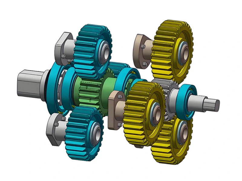
A single planetary stage typically delivers a reduction ratio between 3:1 and 10:1. Most robotic joint actuators require 25:1 to 100:1. Two stages in series, sharing a common housing axis, achieve that range without a proportional increase in radial envelope — which is why the two-stage planetary configuration is the default architecture for compact joints in collaborative robots, exoskeletons, and precision end effectors.
Note: the two ring gears inside that assembly are not doing the same job.
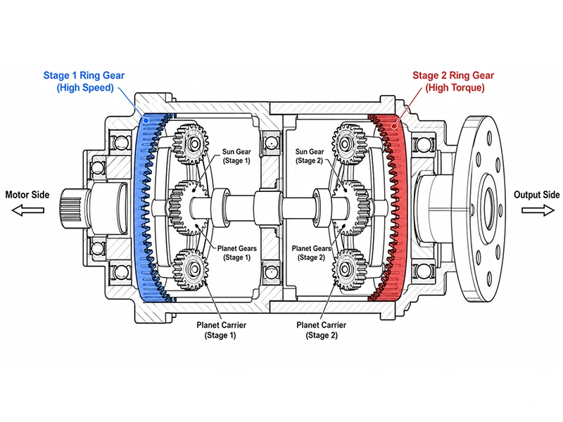
The Stage 1 ring gear sits on the motor side. It sees high rotational speed and relatively low torque — the input has not yet been reduced. Its primary function is accurate planet guidance and efficient load sharing across the planet set. Because of the high input speed, Stage 1 demands tight dynamic tolerances (such as low pitch variation and runout) to minimize high-frequency noise, vibration, and friction losses (NVH).
The Stage 2 ring gear sits on the output side. By the time torque reaches it, the Stage 1 reduction has already multiplied it — in a 30:1 system, the Stage 2 ring gear is managing roughly five to ten times the torque of Stage 1, at a fraction of the speed. In many designs, it is also the component directly interfacing with the output flange or joint housing, often machined directly into the outer structural casing.
From an error-propagation perspective, Stage 2 geometric errors transfer 1:1 to the output, while Stage 1 errors are reduced by the Stage 2 ratio. Thus, Stage 2’s static accuracy (e.g., concentricity and tooth thickness for backlash) directly affects system-level positioning. However, because Stage 2 runs much slower, its dynamic pitch tolerances can be relaxed relative to Stage 1.
Why Ring Gear Tolerances Must Differ Between Stage 1 and Stage 2
Stage 1 Ring Gear (High Speed, Lower Torque)
At Stage 1, the dominant concern is tooth profile accuracy. High meshing frequency amplifies any profile deviation into vibration and noise (NVH). Radial runout matters for planet load sharing, but with torque still low, the consequences of minor variation on tooth strength are limited.
Standard process: Gear shaping or power skiving (note: hobbing is kinematically impossible for internal gears), with achievable accuracy at ISO/GB Grade 6–7. Post-heat-treatment grinding is rarely justified here.
Common drawing mistake: Applying Stage 2 lead tolerance requirements to Stage 1, which unnecessarily forces high-precision hard finishing operations and inflates costs.
Stage 2 Ring Gear (High Torque, Output-Side)
Stage 2 is where tolerance decisions have direct, unmitigated consequences on the final robot joint performance.
Backlash control
Any tooth thickness deviation at Stage 2 transfers directly to output shaft play — there is no downstream stage to absorb it. This typically requires ISO/GB Grade 5–6.
Lead tolerance(Fβ) must be explicitly called out
Under high torque, uneven tooth contact concentrates stress at the tooth edges and accelerates wear. This specification cannot be left to supplier defaults.
Concentricity requires GD&T callouts
Concentricity between the ring gear pitch circle and output bearing seat needs a formal GD&T callout — not just dimensional tolerancing. In compact actuators (ID typically 40–80mm), this axial alignment is where positional repeatability is won or lost.
Surface finish on tooth flanks should reach Ra≤0.8μm
At this torque level, a rough flank surface will cause micro-pitting and rapid wear. However, in compact actuators with a 40–80mm ID — especially those with integrated housing designs — internal gear grinding is often physically impossible due to wheel and spindle clearance constraints.
To reliably achieve this surface finish, the standard industry practice is to utilize Hard Power Skiving after case hardening, or to perform precision skiving/shaping followed by Nitriding (which causes virtually zero thermal distortion, eliminating the need for post-hardening correction).
Why Stage 2 Is the Last Line of Defense(Tolerance Cascade)
In a two-stage system, Stage 1 errors are partially diluted through the gear ratio before reaching the output. Stage 2 errors are not — they transmit directly.
| Parameter | Stage1 Ring Gear | Stage2 Ring Gear |
|---|---|---|
| Speed | High | Low |
| Torque | Low | High |
| Backlash sensitivity | Moderate | Critical |
| Typical accuracy grade (ISO/GB) | 6–7 | 5–6 |
| Recommended process | Shaping / Power Skiving | Hard Power Skiving / Nitriding + Skiving (Grinding where ID geometry permits) |
| Concentricity priority | Moderate | High |
The goal is not uniform precision across both stages — it’s placing manufacturing investment where it changes system output.
What Your Drawing Needs to Say — And What Most Don’t
Three annotation gaps appear consistently in ring gear drawings for two-stage actuators.
Position or Runout (GD&T) on the Stage 2 Bore: Dimensional tolerancing on the inner diameter is not sufficient. Note that under modern ASME Y14.5-2018 standards, the traditional “Concentricity” symbol is deprecated. You should explicitly use a Position or Radial/Total Runout callout relative to your output bearing datum. Without this geometric reference, pitch circle runout will directly degrade joint repeatability and cause rotational binding.
Lead Tolerance (Fβ) Explicitly Stated: For high-torque internal ring gears, Fβ cannot be left to supplier interpretation or inferred from a grade number alone. It needs to appear on the drawing. Omitting it—or failing to specify lead modifications like crowning (Cβ—is how mismatched tooth contact and localized stress concentration get built into production parts.
Heat Treatment Sequence and Stock Allowance: Carburizing and quenching distorts internal gear geometry. If the drawing doesn’t specify whether gear cutting happens before or after heat treatment — and doesn’t call out the correct post-HT hard-finishing stock allowance (e.g., for hard power skiving) or zero-stock parameters for Nitriding — the manufacturer is making that critical process decision for you.
Three Drawing Problems and Their Consequences
Same Tolerance Grade on Both Ring Gears: Either Stage 1 is over-machined at unnecessary cost, or Stage 2 is under-specified and fails to meet backlash requirements at assembly or under load.
Bore Diameter Tolerance Without Cylindricity Requirement: A supplier can hit the diameter band while still delivering an oval or lobed bore (especially on thin-walled integrated housings). Without a cylindricity callout, centering consistency and press-fit pressure across a production batch are left entirely undefined.
No Inspection Method Specified: Standard coordinate measuring machines (CMMs) and dedicated gear measurement equipment report different parameters. Standard 3-axis CMMs with basic touch-trigger probes cannot reliably measure analytical gear parameters like
Fp, Fα, or Fβ. Unless you specify that inspection must be conducted using a dedicated Gear Measuring Center (GMC) or a scanning CMM equipped with professional gear metrology software, you may receive a dimensional report that looks complete but misses the core parameters of gear quality.
What to Ask Your Gear Manufacturer Before Sending the Drawing
These five questions separate manufacturers who truly understand the physical constraints of compact robotic ring gears from those who will approximate it.
“How do you reliably hold ISO/GB Grade 5–6 precision on internal ring gears with a 40–80mm ID after heat treatment?”
Grinding operations can encounter issues such as spindle deflection or grinding wheel interference inside a narrow (or even blind-hole) housing. Manufacturers typically adopt hard power skiving — a process capable of machining gears up to 60 HRC with high precision — or employ a precisely controlled nitriding process, which achieves the required surface hardness without inducing thermal distortion.
“What radial runout or position tolerances can you hold on the integrated ring gear relative to the housing’s bearing datum?”
This size range is where fixturing and clamping deformation become the limiting factors. Ask for a specific runout value (e.g., within 15–20 microns), not a vague ISO grade reference. If the answer is vague, batch concentricity and assembly backlash consistency will be too.
“If we specify carburizing and quenching, how do you correct the resulting internal distortion without relying on internal gear grinding?”
Carburizing and quenching cause internal splines and ring gears to “potato-chip” or shrink unpredictably. A manufacturer without Hard Power Skiving capabilities will have no way to correct this on small internal diameters. Look for a supplier who proactively suggests Nitriding on pre-finished teeth, or who has the specialized hard-skiving machinery to perform post-HT correction.
“Do you inspect analytical gear tolerances (Fα, Fβ, Fp) using a dedicated Gear Measuring Center (GMC) or a scanning CMM with dedicated gear software?”
Standard 3-axis CMMs with touch-trigger probes cannot produce the continuous scan data required to verify pitch error (Fp) or profile deviation (Fα). If your drawing calls out ISO Grade 5 and their inspection report comes from a standard CMM reporting only basic diameters and runout, your gear quality grade remains unverified.
“Can you provide a First Article Inspection Report (FAIR) covering our specified AGMA or ISO class, complete with lead and profile charts?”
A complete FAIR is the traceability link between your CAD drawing and production output. It should include the analytical lead (Fβ) and profile (Fα) inspection charts, material certification, and heat treatment run logs. Without these charts, dimensional conformance on the first article tells you nothing reliable about the actual kinematic quality of the gear teeth.
From Your Drawing to a Production-Ready Ring Gear
Stage 1 and Stage 2 ring gears are not the same specification decision. They differ in load, speed, required accuracy grade, and the manufacturing processes needed to achieve it. Allocating precision where the output demands it — and not uniformly across both stages — is what keeps your robotic drive design manufacturable and your production cost rational.
At Hansheng Automation, we manufacture precision internal and external ring gears for robotic joint and actuator applications, covering custom sizes from ø20mm to ø200mm.
Our process capability is specifically tailored to solve compact actuator challenges, including:
- Precision Gear Shaping & Power Skiving (including Hard Power Skiving for finishing hardened internal profiles without grinding distortion).
- Hobbing & Broaching for high-efficiency external gear and spline production.
- Controlled Nitriding & Case Hardening with minimal thermal distortion.
- Precision Grinding for larger components requiring ISO/GB Grade 5.
Gear accuracy is verified on dedicated Gear Measuring Centers (GMC) and scanning CMMs equipped with analytical gear metrology software (not standard touch-trigger CMMs), and full First Article Inspection Reports (FAIR) are standard on all new part numbers.
If your drawing needs a manufacturability (DFM) review before quoting, our engineering team can turn that around within 48 hours.
FAQ
Can Stage 1 and Stage 2 ring gears share the same housing bore?
Yes, but a straight shared bore forces a packaging compromise. While a straight bore is easier to machine in one setup, it lacks physical axial shoulders for gear positioning. For integrated designs, a stepped bore is preferred to accommodate different module sizes and provide axial locators. If a straight shared bore is used, ensure there is a sufficient tool clearance groove machined between Stage 1 and Stage 2 to prevent tool collision during shaping or skiving.
How does module size affect tolerance achievability on internal ring gears?
Smaller modules (typically below m1.5) leave less material per tooth, making the profile and lead highly sensitive to heat treatment distortion. Achieving ISO/GB Grade 5–6 on a small-module gear (m0.5 to m1.0) requires far tighter control over fixturing, cutting parameters, and hard-finishing than the same grade on a larger module. Always verify your supplier’s demonstrated capability at your specific module range—not just their general grade claim.
What information should I prepare before requesting a quote on custom ring gears?
To get an accurate, comparable quote, please provide:
- A 2D PDF drawing with clear GD&T callouts (especially runout/position relative to datums).
- A 3D CAD step file.
- Specified accuracy grades (ISO, DIN, or AGMA) and spline parameter tables.
- Material specifications and heat treatment requirements (e.g., Nitriding depth or Case Hardness).
- Estimated annual volume and prototype batch sizes.
What is a realistic lead time for prototype vs. production ring gears?
Prototypes (First-Article): Typically 2–4 weeks for internal ring gears requiring shaping or skiving, assuming standard module tooling is available. Parts requiring post-hardening finishing (like hard skiving) may add 1 week.
Production Runs: Typically 4–6 weeks for precision internal ring gears in the ø20–ø200mm range. If your timeline is critical, raise it during the initial DFM review before tooling is ordered.
What does a complete gear inspection report include for ISO Grade 5 ring gears?
A certified ISO Grade 5 report from a dedicated Gear Measuring Center (GMC) or scanning CMM must include:
- Analytical Gear Metrics: Tooth profile deviation (Fα), lead deviation (Fβ), pitch deviation (Fp), and total cumulative pitch error.
- Geometric Tolerances: Bore diameter, concentricity/position, and face runout.
- Traceability Documents: Material certification and heat treatment run logs.
- Note: A standard touch-trigger CMM report showing only diameters and runout does not constitute analytical gear grade verification.