What are the common configurations of a planetary gear train?
Blog 2026-10-12
A simple planetary gear train can transmit, combine, or distribute power through its sun gear, ring gear, and planet carrier. The operating configuration depends on which member receives the input, which member is held stationary, and which member delivers the output. There are 12 common arrangements: six with one member fixed, three with two inputs, and three with one input and two outputs.
How the gears mesh in a planetary gear train
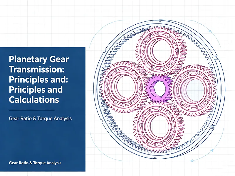
A conventional simple planetary gear train consists of a sun gear, planet gears, an internally toothed ring gear, and a planet carrier.
| Component | Function |
|---|---|
| Sun gear | The central external gear that meshes with the planet gears. |
| Planet gears | Mesh with the sun gear and ring gear. They rotate on their own axes while revolving around the central axis with the carrier. |
| Ring gear | The internal gear that meshes with the planet gears. |
| Planet carrier | Holds the planet gear shafts and moves the planet gears around the central axis. |
The sun gear and planet gears form an external gear mesh. The planet gears and ring gear form an internal gear mesh. The sun gear and ring gear share the same central axis, while the planet gear axes move with the carrier.
The way these components move determines how the planetary gear train transmits power. The gears retain the same basic meshing relationships, but the transmission behavior changes when a different member is fixed or driven.
Six configurations with one member fixed
When one member is held stationary, one of the remaining members can serve as the input and the other as the output. A simple planetary gear train has six possible arrangements of this type.
| Fixed member | Input | Output |
|---|---|---|
| Ring gear | Sun gear | Planet carrier |
| Ring gear | Planet carrier | Sun gear |
| Sun gear | Ring gear | Planet carrier |
| Sun gear | Planet carrier | Ring gear |
| Planet carrier | Sun gear | Ring gear |
| Planet carrier | Ring gear | Sun gear |
Each arrangement produces a different speed relationship.
When the ring gear is fixed and the sun gear drives the planet carrier, the carrier rotates in the same direction as the sun gear at a lower speed. When the planet carrier is fixed, the sun gear and ring gear rotate in opposite directions.
The resulting speed ratio depends on the tooth counts of the sun gear and ring gear. Engineers must therefore consider the fixed member and the selected input-output arrangement when determining the required transmission ratio and rotation direction.
Three configurations that combine two inputs
A planetary gear train can combine motion from two driven members and deliver the resulting motion through the third member. The three possible arrangements are:
- The sun gear and ring gear receive power, and the planet carrier provides the output.
- The sun gear and planet carrier receive power, and the ring gear provides the output.
- The ring gear and planet carrier receive power, and the sun gear provides the output.
These arrangements can be used in differential mechanisms and other systems that combine rotational motion from multiple sources.
The input speeds are linked by the kinematic relationship of the planetary gear train. They cannot be selected independently of the output speed. Torque balance, load conditions, and the drive control system also affect how the mechanism operates in practice.
Three configurations that distribute power to two outputs
A planetary gear train can also receive power through one member while transmitting power through the other two members. The three arrangements are:
- Sun gear input, with the ring gear and planet carrier as outputs.
- Planet carrier input, with the sun gear and ring gear as outputs.
- Ring gear input, with the sun gear and planet carrier as outputs.
These arrangements allow power or motion to be transmitted through two output branches. Their actual behavior depends on the mechanical constraints and operating conditions of the system.
The tooth counts alone do not determine how the input power divides between the two outputs. Output loads, torque reactions, and any additional control or constraint mechanisms also affect the power distribution.
How to calculate the speed relationship
For a simple planetary gear train, the angular speeds of the sun gear, ring gear, and planet carrier follow this relationship:
Where:
- Zₛ is the number of teeth on the sun gear.
- Zᵣ is the number of teeth on the ring gear.
- ωₛ is the angular speed of the sun gear.
- ωᵣ is the angular speed of the ring gear.
- ω꜀ is the angular speed of the planet carrier.
Angular speeds must use a consistent sign convention. The sign of each speed indicates the direction of rotation relative to the chosen reference direction.
This equation allows engineers to calculate the speed relationship between the three members once the necessary operating conditions are known. When selecting a planetary gear configuration, the required speed ratio should be evaluated alongside rated torque, transmission efficiency, backlash, load characteristics, duty cycle, and expected service life.
Planetary gears and robotic joint components
We provide custom manufacturing for planetary gears, robotic joint modules, and related precision mechanical components based on customer drawings and technical specifications.
Have a project in development? Send us your drawings or technical requirements for a review of manufacturing feasibility, critical dimensions, materials, and production requirements.