Spur Gear Manufacturing Process: A Complete Machining Case Study (DIN 6 Precision)
Blog 2026-07-17
This is a shop‑floor case study of the entire spur gear manufacturing process – from blank preparation to final inspection – for a DIN 6 spur gear made of 20CrMnMo, with a Φ65H6 bore and Φ92h5 journal, carburised and induction‑hardened to 58–62 HRC. Every allowance and setup you will see is backed by actual production data.
You will learn why we leave 0.40 mm on the outer diameter before heat treatment, why we choose induction hardening over through‑hardening, and how we restore 6‑grade accuracy through post‑heat grinding. Need a similar gear? Contact us for a quote based on your drawing.
Cylindrical Gear Drawing Analysis – Tolerances, Material & Finish
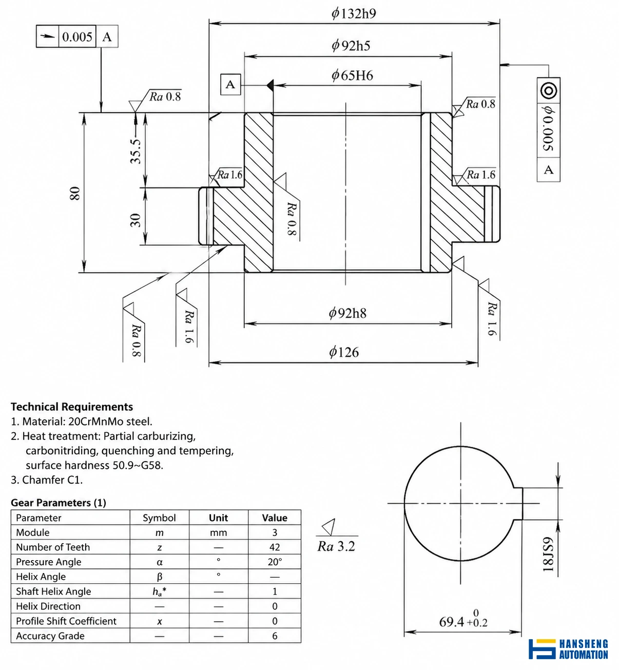
What makes this gear demanding is not a single feature but the combination of tight tolerances on critical mating surfaces. The bore calls for Φ65H6 – an H6 tolerance band that leaves only a few micrometres of clearance for a precision fit, typically used for shaft mounting with minimal runout. The external journal Φ92h5 is equally stringent, specifying a high‑grade shaft journal that must maintain concentricity with the bore. On top of that, the gear is rated at DIN/ISO grade 6, which places it in the precision category – a level where tooth‑to‑tooth errors and cumulative pitch deviations must be rigorously controlled. Meeting all three simultaneously is the core challenge.
Material Selection: Why Choose 20CrMnMo?
Why 20CrMnMo? This carburising steel offers an excellent balance: sufficient hardenability for deep case layers, good core toughness after quenching, and stable response to the specified combined heat‑treatment route – carburising followed by high‑frequency induction hardening and tempering. The target hardness of 58–62 HRC on the tooth flanks ensures wear resistance, while the softer core absorbs shock loads. Surface finish requirements are equally telling: Ra0.8 μm on the bore, journal, and tooth flanks calls for grinding, whereas Ra1.6 μm on other turned surfaces still demands fine turning. These numbers are not arbitrary – they reflect functional needs (sealing, bearing fit, noise reduction) and dictate the entire process sequence.
Spur Gear Manufacturing Process – From Forging to Grinding
The complete route follows three‑stage framework: roughing, semi‑finishing, and post‑heat‑treatment finishing. This separation ensures that thermal distortion during carburising and induction hardening does not compromise final dimensions. The sequence is:
forging → normalising → rough turning → finish turning (semi‑finishing) → hobbing → deburring/chamfering → carburising & induction hardening → keyway broaching → bore grinding → external grinding → gear grinding → inspection.
1: Roughing
- Forging
- Normalising
- Rough Turning
2: Semi-Finishing
- Finish Turning (Semi-Finishing)
- Hobbing
- Deburring / Chamfering
- Carburising & Induction Hardening
3: Post-HT Finishing
- Keyway Broaching
- Bore Grinding
- External Grinding
- Gear Grinding
- Inspection
1.Spur Gear Manufacturing Process – Three Phase Overview
The process is deliberately divided into three phases. 1 (roughing) removes the bulk of stock and establishes basic geometry. 2 (semi‑finishing) brings critical features close to final size, leaving precise grinding allowances. 3 (post‑heat finishing) corrects distortion from heat treatment and achieves the final tolerances through grinding operations. This staged approach is essential for holding DIN 6 accuracy on a carburised gear.
2.Cylindrical Gear Forging & Normalising
The blank is produced by forging on a press, which refines the as‑cast structure and provides a sound fibre flow for subsequent machining. Before any cutting, the forged blanks undergo normalising in a box furnace. This step homogenises the microstructure, refines grain size, and improves machinability – all of which are prerequisites for consistent cutting performance and predictable heat‑treatment response later.
3.Finish Turning – Setting Grinding Allowances for Spur Gears
Rough turning is carried out on a conventional horizontal lathe (Operations 10–30). The outer diameter is roughed to Φ94 mm, and the bore is drilled and bored to Φ63 mm – leaving substantial stock for the semi‑finishing stage. The allowance at this stage is generous (typically 2–3 mm per side) to remove decarburised surface layers and to accommodate any runout from the forging. The workpiece is turned end‑to‑end with a self‑centring chuck, establishing initial squareness and length references.
4.Finish Turning (Semi‑Finishing)
This is performed on a CNC lathe (Operation 40) and represents the critical semi‑finishing step. The sequence is as follows:
- First setup: Chuck on the roughed Φ92 mm diameter. Face the end to a total length of 81.10 mm, leaving 0.10 mm for final grinding on that face.
- Turn the Φ92h8 external diameter to its finished nominal size, achieving Ra1.6 μm – this surface will not be ground later.
- Bore the Φ65H6 hole to Φ64.65H7, leaving 0.35 mm for internal grinding after heat treatment.
- Turn the Φ132h9 outer diameter to size.
- Chamfer all edges as per the drawing.
Second setup: Flip the workpiece, chuck on the newly turned Φ92h8 diameter. Face the opposite end to set the overall length at 80.10 mm.
The Φ92h5 journal is semi-finished with a 0.40 mm grinding allowance. This specific value balances two key factors: expected thermal distortion (typically 0.02–0.05 mm radial runout) from carburizing and induction hardening, and the minimum stock needed for final cylindrical grinding to meet h5 tolerance and Ra0.8 μm finish. Too little risks incomplete cleanup; too much increases grinding time and heat risk.
Finally, machine all remaining chamfers and tooth tip chamfers as specified.
At the end of finish turning, all features are within 0.10–0.40 mm of final size, ready for hobbing and subsequent heat treatment.
5. Spur Gear Hobbing – 0.20mm Grinding Allowance
Hobbing (Operation 50) is performed on a Ningjiang YK3610Ⅳ CNC horizontal gear hobbing machine (max. module 3, max. workpiece diameter 200 mm). At this stage, the gear teeth are cut to a semi‑finished profile, leaving a grinding allowance of 0.20 mm on each tooth flank. This stock is precisely calculated: it is sufficient to remove the decarburised layer and correct any thermal distortion during subsequent hardening, yet thin enough to make gear grinding efficient. To ensure uniform allowance after heat treatment, the hobbing process must control tooth profile, lead, and runout within tight limits – typically holding an AGMA/DIN class 8–9 quality prior to grinding. Any significant indexing error at this stage cannot be fully corrected later, so the machine setup, cutter sharpness, and workpiece clamping are monitored rigorously.
6.Deburring & Chamfering – Edge Preparation for Gear Teeth
Operation 60 is a manual bench operation. All burrs generated by hobbing are carefully removed, and the tooth tips and edges are chamfered per the drawing requirements. This step is often underestimated, but it is critical: sharp burrs can cause stress concentration during carburising and may lead to edge cracking. A clean, smooth tooth contour also ensures consistent case depth distribution along the tooth profile.
7.Carburising & Induction Hardening for Cylindrical Gears
The gear undergoes a combined case‑hardening cycle (Operation 70). First, carburising in a controlled‑atmosphere furnace builds a case depth of 0.9 mm to 1.3 mm – a range specified to provide adequate wear resistance while maintaining core toughness. The depth is controlled by time, temperature, and carbon potential, with test coupons monitored throughout the cycle.
After carburising, the gear is high‑frequency induction hardened and tempered to a final tooth flank hardness of 58–62 HRC. Why induction hardening instead of through‑hardening or conventional re‑heating? Induction hardening offers two decisive advantages: it localises the heat input to the tooth flanks, minimising overall distortion; and it allows precise control of the hardened layer, preserving the core’s ductility. This is especially beneficial for a precision gear, because distortion directly affects the remaining grinding allowance.
Nevertheless, heat treatment inevitably introduces some distortion – a typical loss of 1–2 ISO/DIN grades is expected after hardening. That is precisely why we reserved grinding stock on the bore, the journal, and the teeth. The subsequent grinding operations will correct these deviations and restore the final 6‑grade accuracy.
Heat treatment is a make‑or‑break step in gear manufacturing. We maintain an in‑house heat‑treatment chain – from carburising furnaces to induction equipment and tempering ovens.
Cylindrical Gear Machining – Post Heat Treatment Operations
After heat treatment, the gear has hardened surfaces but also some degree of distortion – runout, ovality, and pitch errors typically worsen by 1–2 grades. The following operations do not merely remove stock; they systematically correct these deviations, re‑establish geometric relationships, and bring the part to its final 6‑grade accuracy. All post‑heat machining is performed with careful locating schemes to preserve the bore‑to‑tooth axis relationship, using equipment capable of holding the required tolerances – including our gear grinding machines which are qualified to 5‑grade precision capability.
1 Keyway Broaching in Cylindrical Gear Machining
Broaching the internal keyway (Operation 80) is intentionally scheduled after heat treatment, using a Nachi broaching machine for clean, single‑pass slot cutting. Why? Because carburising and induction hardening leave the bore and the keyway zone with a hard, wear‑resistant surface, but distortion in the keyway area is minimal compared to the gear body. Performing broaching at this late stage ensures that the keyway position – referenced from the bore and the end face – remains true to the final bore geometry. A broaching tool cuts a clean, accurate slot in one pass, and a slot gauge is used for immediate in‑process verification.
2 Internal Bore Grinding
The bore is ground on a CNC internal grinding machine (Operation 90). The workpiece is clamped on the already‑turned Φ92h5 journal, and alignment is performed by referencing the right end face and the pitch circle of the gear. This dual reference ensures that the bore axis is perpendicular to the end face and concentric with the pitch circle, which is the functional datum for gear operation.
The Φ65H6 bore is ground to final size, achieving a surface finish of Ra0.8 μm.
The right end face is then face‑ground (by the same setup) to Ra0.8 μm, ensuring perpendicularity to the bore.
At this point, the internal datum – bore and end face – is fully established to its final accuracy.
3 External Cylindrical Grinding
The external journal Φ92h5 is ground on a cylindrical grinder (Operation 100). The key detail is the mounting method: the gear is installed on a taper arbor that locates precisely in the newly ground Φ65H6 bore. This arbor ensures that the external grinding operation is concentric with the bore – a prerequisite for maintaining the h5 tolerance and runout requirements. The journal is ground to final diameter and Ra0.8 μm, with the arbor guaranteeing that the bore‑to‑OD coaxiality stays within the design limits.
4 Gear Grinding for DIN 6 Spur Gear Accuracy
Final tooth finishing is performed on a gear grinding machine (Operation 110). Here again, the workpiece is located on a taper arbor through the Φ65H6 bore – the same datum used for external grinding. This consistent, bore‑based referencing is what ultimately ties the tooth profile, the bore, and the journal into one geometrically coherent assembly.
Gear grinding is the decisive operation for achieving DIN 6 precision. While hobbing provides a shaped tooth, only grinding can correct the cumulative pitch errors, profile deviations, and lead errors that arise from heat‑treatment distortion. The 0.20 mm allowance left on the tooth flanks is now removed by the grinding wheel, generating a case‑hardened surface with Ra0.8 μm finish and a smooth, accurate involute.
Quality Inspection & Control
Using dedicated gauges and instruments, we measure every critical feature against the drawing. A smooth plug gauge checks the bore for size and roundness, a slot gauge verifies the keyway, and a taper arbor assesses bore‑to‑OD concentricity and runout. We perform all measurements on a dedicated gear inspection instrument following DIN 3960 / ISO 1328 evaluation standards, and our gauges are regularly calibrated to national traceability requirements. Beyond these, the inspection regimen covers:
- Bore size, roundness, and surface finish (Ra0.8 μm)
- External journal diameter, cylindricity, and finish
- Tooth accuracy – profile deviation, lead error, and cumulative pitch error
- Surface roughness on all ground features
We reference all measurements to the established datums. For the DIN 6 gear rating, we apply the standard tolerance grades to each parameter: individual pitch errors must fall within specified micrometre limits, total cumulative pitch deviation must not exceed the grade‑6 threshold, and we assess both profile and helix deviations over the full tooth width. We segregate and review any non‑conforming part.
Gear Manufacturing Challenges – & How We Solve Them
Three main challenges define this DIN 6 project.
Heat treatment distortion is the most significant. Carburizing and induction hardening typically degrade accuracy by 1–2 DIN grades through runout, ovality, and pitch errors. We counter this with proven pre-heat allowances: 0.35 mm on the bore, 0.40 mm on the journal, and 0.20 mm on tooth flanks.
Consistent datum referencing prevents error accumulation. By using the bore and end face as primary datums from rough turning through final grinding—and employing the same taper arbor for external and gear grinding—we maintain coaxial relationships across operations.
Holding stable DIN 6 accuracy requires tight process control. Our three-phase approach (roughing, semi-finishing, and post-heat corrective grinding) ensures the final gear grinding step can correct accumulated deviations effectively.
Custom Cylindrical Gear Machining – Conclusion
This case demonstrates our ability to manage the full process chain – forging, turning, hobbing, carburising and induction hardening, and precision grinding of the bore, journal, and teeth – while consistently holding DIN 6 accuracy on carburised gears. The data you have seen (0.35 mm bore allowance, 0.40 mm OD allowance, 0.20 mm tooth allowance) reflects real production experience, not textbook estimates.
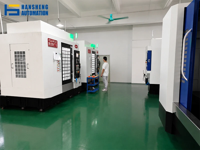
We handle custom gears across a wide range of materials, sizes, and precision classes – from prototypes to medium and high‑volume batches. Our capabilities include hobbing, shaping, grinding, internal/external cylindrical grinding, and in‑house heat treatment and inspection.
Send us your drawing today. We will respond with a process proposal, realistic lead times, and firm quality commitments. Let us show you how we turn demanding specifications into delivered parts.
FAQ
Forging → normalising → rough turning → finish turning → hobbing → deburring → carburising & induction hardening → keyway broaching → bore grinding → external grinding → gear grinding → inspection.
20CrMnMo is a common choice for its good hardenability and balanced core/toughness properties. Alternatives such as 20CrMnTi or 17CrNiMo6 may be used, but process parameters and allowances must be adjusted accordingly.
We use three measures: pre‑hardening grinding allowances (bore 0.35 mm, OD 0.40 mm, tooth flanks 0.20 mm); consistent bore‑and‑face locating throughout all operations; and post‑hardening grinding to remove any runout or ovality.
Hobbing is a cutting process that generates tooth profiles economically but typically holds only DIN 8–9 accuracy. Gear grinding is an abrasive finishing operation that corrects pitch, profile, and lead errors, and is required to achieve DIN 6 with Ra0.8 μm surface finish.
DIN 6 (ISO grade 6) is a precision class with tight micrometre‑level limits on pitch, profile, and helix deviations. It is used for high‑speed, low‑noise applications and requires grinding as the final tooth finishing step.
In this case, 0.20 mm per flank after hobbing. For the bore and external journal, allowances are 0.35 mm and 0.40 mm respectively – all derived from actual distortion data to ensure reliable clean‑up after heat treatment.