Large Worm Gear Manufacturing Case Study: Drawing Analysis & Complete Manufacturing Process
Blog 2026-07-06
Large cast iron worm gears are manufactured via a sequence of casting, heat treatment, rough turning, stress relief aging, finish turning, hobbing, and inspection. The key challenges are bore accuracy, deformation control, and bore to tooth concentricity. Manufacturers usually perform rough machining before artificial aging to release residual stresses, followed by finish machining in a single setup to achieve precise datum alignment.For large worm gears, skipping this sequence often results in dimensional movement during finish machining, making it difficult to maintain bore accuracy and gear concentricity. Finally, the finished bore is used as the hobbing reference to improve meshing accuracy.
At hansheng, we support this complete workflow by offering professional worm gear manufacturing and precision machining services, adhering to rigorous industrial standards from raw casting through to final inspection.
This article explains each stage of the manufacturing process, the every operation, and the practical techniques used to produce high-precision large worm gears for heavy-duty transmission applications.
Understanding the Engineering Drawing: Critical Dimensions and Technical Requirements
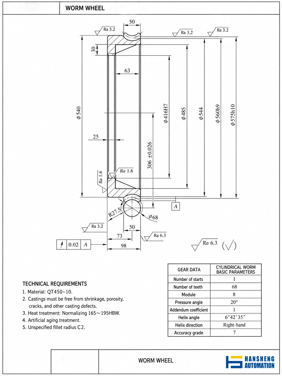
According to the analysis of the drawings, this large worm gear emphasizes several strict dimensional and geometric tolerances, which are crucial for ensuring correct gear meshing and reducing transmission noise.
Material Specification and Heat Treatment
- Material: QT450-10 (Ductile Iron).
- Normalizing Hardness: The raw casting undergoes a normalizing heat treatment to achieve an initial hardness of 170-180 HBW (specified as 165-195 HBW after final thermal processing).
- Stress Relief: An artificial aging process is mandatory after rough machining. This stage is critical for eliminating internal casting and machining stresses, preventing subsequent dimensional distortion during finish machining.
Key Dimensional Tolerances
- Central Bore (φ416H7): As the primary mounting and locating datum, this bore requires high precision (H7 tolerance class) and a low surface roughness of Ra 1.6 um to guarantee a precise shaft fit.
- Outer Diameter (φ575h10): This serves as the addendum circle. It is finished to an h10 tolerance, establishing a precise outer diameter reference.
- Total Length (98 mm) and Step Thickness (25 mm): Operators must maintain the overall axial length at 98 mm (with a surface finish of Ra 1.6 um on both end faces) and hold the left step thickness at 25 mm.
- Gear Width (51 mm): The tooth face width is machined to exactly 51 mm at the φ575h10 outer rim.
Geometrical Relationships and Surface Integrity
- Coaxiality and Perpendicularity: To prevent axial runout and meshing errors, operators must machine the left end face and the φ416H7 bore in a single setup (one-time clamping) during finish turning. This ensures that the reference face is strictly perpendicular to the bore axis, which is a prerequisite for high-precision gear hobbing.
- Surface Roughness: Mating and locating boundaries–specifically the bore (φ416H7), left face, and right face–must achieve a fine finish of Ra 1.6 um. Non-mating outer diameters, such as the φ540 flange, are held to Ra 3.2 um.
Material Selection: Why QT450-10 is Chosen
Selecting QT450-10 (ductile iron) for large-scale worm gear manufacturing is driven by its mechanical properties, tribological performance, and cost-efficiency.
Excellent Tribological Properties and Wear Resistance
Worm drives operate under high sliding friction. The spherical graphite nodules in QT450-10 act as solid lubricants, reducing the friction coefficient, mitigating scuffing, and prolonging gear set life.
Superior Vibration Damping
Compared to steel, ductile iron offers exceptional damping capacity. The graphite phase absorbs vibrations and noise, ensuring quieter operation and reducing structural resonance in large industrial gearboxes.
High Ductility and Impact Toughness
Unlike brittle gray cast iron (e.g., HT200), QT450-10 delivers a minimum tensile strength of 450 MPa and 10% elongation. This ductility allows gear teeth to withstand shock loads and bending stresses without brittle fracture.
High Casting Quality and Machinability
For large diameters, machining from solid steel blanks is prohibitively expensive. QT450-10 castings exhibit excellent fluidity to minimize porosity and shrinkage, while offering high machinability that reduces tool wear and machining times.
Cost-Effectiveness
While high-tin bronze (e.g., ZCuSn10Pb1) is a premium choice for smaller gears, its cost is economically unviable for extremely large sizes. Paired with a hardened steel worm, QT450-10 provides a cost-effective alternative for medium-speed, high-torque industrial applications.In practice, it also offers more stable machining performance than large steel forgings, which are generally more prone to distortion after heavy material removal.
Key Manufacturing Challenges in Large Worm Gear Production
Based on the technical requirements in the drawings, the primary difficulties lie in controlling large-bore accuracy, ensuring precise geometric alignment, and managing material deformation.
High-Precision Machining of the Large Bore (φ416H7)
Finishing a central bore of φ416 to an H7 tolerance class is technically demanding. During rough turning (, the bore is only machined to φ414. Achieving the final H7 limit and a surface roughness of Ra 1.6 um during finish turning (Step 50) requires extremely rigid internal boring tools to prevent chatter and deflection. As the boring bar overhang increases, even minor vibration can lead to tapered bores, poor surface finish, and difficulty maintaining the H7 tolerance.
Coaxiality and Perpendicularity via Single-Setup Machining
A critical constraint in the process analysis requires operators to turn the left end face and the φ416H7 bore in a single setup (one-time clamping). If operators machine these features in separate setups, re-clamping errors will inevitably introduce geometric runout. Although each individual operation may still fall within tolerance, the accumulated positioning errors can significantly affect the final gear meshing accuracy. Maintaining strict perpendicularity between the bore axis and the end face is vital because these two surfaces serve as the positioning datums during the subsequent gear hobbing phase.
Stress-Induced Deformation Control
With a large casting allowance of 8 mm per side, rough machining removes a massive volume of metal. This aggressive material removal releases significant residual casting and machining stresses. If operators performed finish turning immediately afterward, these stresses would cause the blank to gradually warp over time, distorting the φ416H7 bore and the axial dimensions.
To prevent this, the process inserts an artificial aging heat treatment directly between rough turning and finish turning . This aging step relieves internal stresses, stabilizing the workpiece’s microstructure so that critical dimensions—such as the total length of 98 mm and the gear width of 51 mm—remain stable after final machining.
Minimizing Clamping Distortion on Large-Diameter Blanks
Clamping a φ575h10 blank using a self-centering chuck requires precise jaw pressure control. Excessive clamping force on these thin-walled or large-diameter sections can cause elastic deformation. Once the chuck is released, the material springs back, distorting the roundness of the φ416H7 bore. The process manages this risk by carefully transitioning the clamping zones—such as clamping the φ575h10 outer diameter for the initial operations, and then switching to the already machined φ540 outer diameter for the final turn-around steps—to distribute clamping forces safely.
Simplified Process Flow
1: Casting
The blank is cast using QT450-10 ductile iron, leaving an 8 mm machining allowance on each side.
2: Heat Treatment: Normalizing
A normalizing process is carried out in a box furnace to stabilize the material hardness to a range of 165–195 HBW.
3: Rough Turning
Heavy metal cutting is performed to remove the majority of machining allowance efficiently. Rather than pursuing dimensional accuracy at this stage, the primary objective is to remove material uniformly while minimizing the introduction of additional machining stresses.
4: Heat Treatment: Artificial Aging
An artificial aging process is executed immediately after rough turning to relieve internal casting and machining stresses.
5: Finish Turning
High-precision finishing is performed on a horizontal lathe. The reference left end face and the φ416H7 bore are finished in a single setup (one-time clamping) to ensure absolute perpendicularity.
6: Gear Hobbing
Using the finished left end face and the φ416H7 bore as primary positioning datums, the gear teeth are hobbed to their final precision after aligning the center distance and center height.
Large Worm Gear Manufacturing Detailed Machining Process
Executing the manufacturing process for a large-diameter worm gear requires careful coordination between mechanical cutting and thermal treatments. Below is a detailed, step-by-step analysis of each phase, combined with practical engineering insights.
Phase 1: Casting (Operation 10)
Process: Cast the blank using QT450-10 ductile iron with an 8 mm single-side machining allowance.
A generous 8 mm machining allowance is essential for large sand-cast parts. It ensures that any casting defects near the skin—such as slag inclusions, surface porosity, sand burning, or decarburization—are completely removed during rough machining, exposing the dense, high-strength graphite-ferrite matrix underneath.
Phase 2: Heat Treatment—Normalizing (Operation 20)
Process: Thermal processing in a box furnace to achieve a target hardness of 165–195 HBW.
Normalizing refines the grain structure of the QT450-10 ductile iron. It breaks down coarse, as-cast dendritic pearlite and ferrite into a highly uniform microstructure. This specific hardness range (165–195 HBW) represents the “optimal hardness window” for machining: it provides enough mechanical strength for the finished gear teeth while keeping the shear resistance low enough to prevent severe tool wear during subsequent turning.
Phase 3: Rough Turning (Operation 30)
Performed on a robust horizontal lathe, this phase focuses on rapid material removal (High Material Removal Rate) to shape the core geometries of the blank.
- (Face Left Side): Clamp the raw casting’s outer diameter (φ575h10) using a self-centering chuck. Align, clamp, and face the left end face until it is clean and flat to establish a basic machining reference. (Tool: 45° offset turning tool)
- Turn Small OD): Turn the φ540 outer diameter down to φ542, leaving a length of 48 mm. (Tool: 90° cylindrical turning tool)
- (Rough Bore): Rough bore the central hole to φ414, leaving 2 mm of stock for final precision boring. (Tool: Internal boring bar)
- (Turn Around & Face Right Side): Flip the workpiece. Clamp onto the rough-turned φ540 outer diameter. Align, clamp, and face the right end face to establish a rough overall length of 100 mm (leaving 2 mm of stock). (Tool: 45° offset turning tool)
- (Turn Large OD): Rough turn the large outer diameter (φ575h10) down to φ577. (Tool: 90° cylindrical turning tool)
During rough turning, the clamping forces must be carefully adjusted. Since cast surfaces are irregular, using a self-centering chuck requires manual dialing/alignment to balance the runout. Leaving exactly 2 mm of stock on the critical bore (roughing to φ414 instead of φ416) and 2 mm on the length ensures there is sufficient material to correct any structural warping caused by stress release.
Phase 4: Stress Relief—Artificial Aging (Operation 40)
Process: Controlled artificial aging thermal cycle.
This is a critical transition step. Rough machining removes a massive volume of cast metal, disrupting the internal stress equilibrium. Without intermediate stress relief, the blank would slowly warp over the following days or weeks, causing the finished φ416H7 bore to lose its roundness and tolerance. The artificial aging cycle (typically heating to 500–550°C, holding, and slow cooling) relaxes these residual stresses, stabilizing the component’s geometry before high-precision finishing.
Phase 5: Finish Turning (Operation 50)
Performed on a high-precision horizontal lathe, this stage defines the final dimensional and geometric accuracy of the gear blank.
- (Finish Left Face): Clamp the φ575h10 outer diameter. Align, clamp, and finish turn the left end face, holding the step dimension to 25 mm with a fine surface finish of Ra 1.6 um. (Tool: 45° offset turning tool)
- (Finish Small OD): Finish turn the φ540 outer diameter to drawing specifications, achieving a surface roughness of Ra 3.2 um. (Tool: 90° cylindrical turning tool)
- (Finish Gear Rim Face): Face the step on the φ575h10 outer diameter to guarantee a finished gear face width (tooth thickness) of exactly 51 mm. (Tool: 90° cylindrical turning tool)
- (Finish Bore): Precision bore the central hole to its final dimension of φ416H7, achieving a strict surface roughness of Ra 1.6 um. (Tool: Internal boring bar)
- (Chamfering): Cut a C2 chamfer on the left internal bore and a C2 chamfer on the outer diameter. (Tool: 45° offset turning tool)
- (Turn Around & Finish Right Side): Flip the part. Clamp onto the finished φ540 outer diameter. Align, clamp, and finish turn the right end face to secure a final total length of 98 mm with a surface finish of Ra 1.6 um. (Tool: 45° offset turning tool)
The core technical achievement here is completing Steps 5.1 through 5.6 in a single, uninterrupted setup. Once the locating bore and reference face are established together, every subsequent operation can reference the same machining datum, significantly reducing cumulative positioning errors. Machining the reference left face (Step 5.1) and the central locating bore (Step 5.4) without unclamping the workpiece guarantees absolute perpendicularity between the bore axis and the mounting face..
Phase 6: Gear Hobbing (Final Cutting Phase)
Process: Set up the blank on the hobbing machine, locating it by the finished left end face and the φ416H7 bore. Establish the correct center distance and center height, and hob the teeth.
Hobbing a large worm gear requires flawless datum registration. The φ416H7 finished bore is placed over a precision expanding mandrel, and the flat left end face is clamped tightly against the machine’s fixture table. Because these two surfaces were turned in a single setup, the blank revolves with zero axial or radial wobble relative to the hobbing machine’s rotational axis. This ensures that the cut teeth have a uniform profile, a correct lead angle, and precise tooth spacing, preventing premature wear and operational noise when meshed with the worm.
Conclusion
The precision of a large worm gear is determined by the entire manufacturing process—not by gear hobbing alone. Careful control of casting quality, stress relief, machining datums, and finish machining is essential for achieving stable dimensions, accurate tooth geometry, and reliable service performance.
At Hansheng Automation, we combine proven manufacturing processes with heavy-duty machining capabilities to produce custom large worm gears that meet demanding engineering requirements. If you have a technical drawing or project requirement, our engineering team is ready to evaluate your design and recommend the most suitable manufacturing solution.
FAQ
Large worm gears are typically manufactured through casting, normalizing, rough turning, artificial aging, finish turning, gear hobbing, and final inspection. This sequence helps maintain dimensional stability, accurate gear geometry, and reliable performance under heavy-duty operating conditions.
Artificial aging relieves residual stresses released during rough machining. Without this step, large castings may gradually deform before finish machining, making it difficult to maintain bore accuracy, concentricity, and overall dimensional stability.
QT450-10 ductile iron offers an excellent balance of strength, wear resistance, vibration damping, and machinability. Compared with machining large steel forgings, it also provides a more economical solution for medium- and high-torque industrial transmission applications.
Yes. Large worm gears are commonly manufactured based on customer drawings and technical specifications. The production process, material selection, heat treatment, machining sequence, and inspection methods can all be customized to meet specific application and performance requirements.